With the inside surfaces sealed, light temporary frames, about 20mm thicker than the sashes, were lightly fitted into the four corner openings. The frame was then flipped over and rested on these frames, which protected the inside finish.
The entabulature, fixed to the outside face of the transom rail was tackled first. The "Cyma reversa" moulding, being the most difficult section to produce, was machined from some Lebanese cedar using multiple bits and a number of passes over the router table. Once it was ready, fine tuning of the dimensions for the other components could be completed. The frieze pattern, cut out from 6mm Hoop pine marine ply, was varied slightly in the horizontal plane in order to match on the mitres. The "Cap" was machined to a tapered profile and was mitred over all the projections. This had the top surface sloping outwards to prevent the pooling of any moisture.
The untrimmed pieces for the two ends have been left loose at this stage. They will be trimmed to fit neatly against the stone reveals, once the frame is installed.
Making the proverbial "Silk purse from a sows ear".applied to the making of the turned columns. From my stash of "accumulated" timber, I grabbed the most accessible pieces that were of sufficient dimensions and durability, some old 5 inch square, Red gum and Jarrah verandah posts, complete with cracks, charred faces and embedded nails. The nails, some of which had been previously broken off and were hard to detect, obviously needed to be removed, hence the chiseled holes seen in the photo. Only one was missed and ultimately discovered by the roughing gouge when on the lathe!. All the pieces had deep cracks along one face, however as the columns are planed flat at the back, to fit against the mullions, these could be hidden there.
The small shoulders on the ends were cut on the bandsaw for mounting in the lathe chuck, once roughed down, (at a very low speed), a truer rounded shoulder was shaped alongside and the square section cut off. With the blank remounted, a 1 inch diameter hole was drilled in the opposite end to accommodate the "live centre", this hole would be used for dowelling the finished pieces together. The blanks were then returned, down to about 105mm diameter and roughly shaped, as seen in the above photo. The lathe speed was then cranked up for pieces to be finished off and sanded.
The next step was the "fluting" to the lower half of the columns, this I
was able to do this on my lathe. I attached my little trimming router
to a flat base which would slide on a fabricated a table, bolted onto
the lathe bed, all adjusted to align with the horizontal centre line of
the work. After much thought on how I could make up an indexing head for
the purpose, I found that the shaft lock on the head would serve,
having 12 separate positions. Excess slop in the spindle with this
method was overcome by filing down a screwdriver shaft to as tight a fit
in the locking hole as possible and then clamping it down firmly for
each flute.
More than happy with the results, the first one is completed and the next is waiting for it's turn in the lathe. I opted to turn the bases separately, as the total length of the columns was too long for my lathe. The pieces, as they are, only just fitted between the centres.
I put much thought into how to decorate the upper section, finding the originals I was emulating, a little plain in this area. I chose to continue the same style of column through, topped off with Doric capitals, as seen in the above picture of the dry fitup. These would be a little less heavy than the Corinthian capitals, that would be topping off the lower columns, and the subject of my next post.
Not having any suitable timber of sufficient size to turn the larger diameter, I laminated some pieces of Lebanese cedar for the purpose. Using this instead of hardwood was not only much easier to turn, especially given the large volume of wood to be removed, it was also less vicious on the tools.
Thursday, May 2, 2013
Thursday, April 11, 2013
72, Front Door, part 3.
Having some time elapse since my attentions were drawn away from the door frame construction proved to be rather advantageous. The Celery top pine, on the dry fitted assembly, which I had assumed was very stable and had been sufficiently seasoned, shrunk somewhat in the dry summer heat.
The worst affected area was the joints on the large transom rail, where it crosses the mullions. The shrinkage caused the joints to open, creating an unsightly 2mm gap. This seemed quite excessive, but, given the width of this rail, the amount of movement was less than 1%.
Fortunately, with the inside face of the rail needing some form of embellishment, the fix was rather simple.
Firstly, I routed a 100mm wide rebate out along the centre line, 18mm deep, then sawed the piece in half.
When reassembling the frame, the two halves were wedged apart to tighten the joints. Then neatly cut infill blocks were inserted, to line up with the mullions.
Lebanese cedar veneer was then laminated to some 3mm ply, which I placed in the bottom of the rebate before the application of bolection mouldings. It did seem a pity to hack into such a nice section of timber, but as mentioned earlier, it needed some form of decoration.
With the main frame now permanently assembled and prior to inverting the whole unit, the inside face received a light staining and a couple of coats of clear lacquer. This would save any extra flipping of the heavy unit and protect the surface from any moisture damage. My main fear at this stage is from the risk of the resident "leaky" possums, who enjoy scurrying around on the exposed joists overhead. These, I am unable to exclude from the house, until the door and frame are completed and installed.
The joining of the lower rails to the mullions and jambs needed to be very solid. They would need to withstand any movement generated by the swinging and slamming of the door. To keep it all tight I drilled right through from the outer edges to within about 20mm of the door rebates on the mullions.
Pockets were drilled in from the outside face to intersect with the ends of the holes These allow for the fitting of washers and nuts to10mm threaded rod, which was pushed through the hole from the opposite end and they will later be covered with the frame pedestals.
The worst affected area was the joints on the large transom rail, where it crosses the mullions. The shrinkage caused the joints to open, creating an unsightly 2mm gap. This seemed quite excessive, but, given the width of this rail, the amount of movement was less than 1%.
Fortunately, with the inside face of the rail needing some form of embellishment, the fix was rather simple.
Firstly, I routed a 100mm wide rebate out along the centre line, 18mm deep, then sawed the piece in half.
When reassembling the frame, the two halves were wedged apart to tighten the joints. Then neatly cut infill blocks were inserted, to line up with the mullions.
Lebanese cedar veneer was then laminated to some 3mm ply, which I placed in the bottom of the rebate before the application of bolection mouldings. It did seem a pity to hack into such a nice section of timber, but as mentioned earlier, it needed some form of decoration.
With the main frame now permanently assembled and prior to inverting the whole unit, the inside face received a light staining and a couple of coats of clear lacquer. This would save any extra flipping of the heavy unit and protect the surface from any moisture damage. My main fear at this stage is from the risk of the resident "leaky" possums, who enjoy scurrying around on the exposed joists overhead. These, I am unable to exclude from the house, until the door and frame are completed and installed.
The joining of the lower rails to the mullions and jambs needed to be very solid. They would need to withstand any movement generated by the swinging and slamming of the door. To keep it all tight I drilled right through from the outer edges to within about 20mm of the door rebates on the mullions.
Pockets were drilled in from the outside face to intersect with the ends of the holes These allow for the fitting of washers and nuts to10mm threaded rod, which was pushed through the hole from the opposite end and they will later be covered with the frame pedestals.
Thursday, March 28, 2013
71, Flashing.
With the summer fire season setting in and after having completed much work in clearing hazards around the property, I could see that the biggest threat to our safety would be from ember attack. Most major bushfire's, in this part of the world, are fanned by strong, hot northerly winds. These normally change to blustery south westerlies when the cool changes arrive later on in the day. Fuelled by the oil rich eucalypt vegetation, the firestorms also create their own updrafts drawing all manner of burning material higher into the atmosphere and depositing it up to tens of kilometers in advance. I have vivid recollections of the Ash Wednesday fires, on the 16th of February, 1983. At that time, I was working on a car at my parents house in Torquay when, without warning, the sky suddenly turned black and burning embers began fluttering to the ground. This was one of the most terrifying moments of my life, I had no prior warning of the situation and it seemed like Armageddon had arrived!. That moment was when the wind changed direction, the fire had already been roaring in a southerly direction for a few hours and was still some 30kms distant, south west from us, near Lorne.
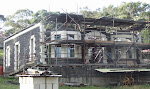
The temporary roofing, which I had installed over the ground floor, was originally only for the purpose of keeping the rain off the framing timber and to provide a dry work area. The gaps around the perimeter were sheltered by the higher roof sheeting on the scaffold. Now, with the ground floor near to being fully sealed following the installation of the windows, flashing's were moved to the top of the priority list. Wind blown embers, entering any internal cavities would spell disaster.
Being the bowerbird that I am, I had already accumulated a large assortment of odd flashings and sheeting. My supply, however, proved to be only barely adequate, I had seriously underestimated the amount required, not to mention the work involved in installation.
The job entailed the fitting of double folded flashings over the sheet ribs and up the inside of the stone walls, which were overlapped by apron flashings set into the horizontal mortar joints. The recessed door and widow openings, with their angled reveals, proved to be the most fiddly. The majority of these were formed to suit on my home made sheet folder, after being cut (and flattened) from the myriad of pieces I had collected.
More than a month was to pass before it was finally completed, but at least now I had some peace of mind. I can only hope that it ultimately proves to have been unnecessary!.
Stepped flashings were also fitted where the roofing on the original house abuts the "extension". Later, these will need to be replaced with permanent colorbond ones, once all the stonework is completed and the scaffold is removed.
The temporary roofing, which I had installed over the ground floor, was originally only for the purpose of keeping the rain off the framing timber and to provide a dry work area. The gaps around the perimeter were sheltered by the higher roof sheeting on the scaffold. Now, with the ground floor near to being fully sealed following the installation of the windows, flashing's were moved to the top of the priority list. Wind blown embers, entering any internal cavities would spell disaster.
Being the bowerbird that I am, I had already accumulated a large assortment of odd flashings and sheeting. My supply, however, proved to be only barely adequate, I had seriously underestimated the amount required, not to mention the work involved in installation.
The job entailed the fitting of double folded flashings over the sheet ribs and up the inside of the stone walls, which were overlapped by apron flashings set into the horizontal mortar joints. The recessed door and widow openings, with their angled reveals, proved to be the most fiddly. The majority of these were formed to suit on my home made sheet folder, after being cut (and flattened) from the myriad of pieces I had collected.
More than a month was to pass before it was finally completed, but at least now I had some peace of mind. I can only hope that it ultimately proves to have been unnecessary!.
Stepped flashings were also fitted where the roofing on the original house abuts the "extension". Later, these will need to be replaced with permanent colorbond ones, once all the stonework is completed and the scaffold is removed.
Saturday, January 12, 2013
70, Some flooring and Trimming.
During the past months, not all my time was wasted, tinkering with the Rotary convertor.
Two separate lots of decent secondhand chipboard flooring came up on eBay at reasonable "Buy it now" prices. It was just nicely enough to sheet the floor in the remaining ground floor rooms. It is only intended to be temporary and was lightly screwed to alternate joists. The permanent timber strip flooring, to avoid any possible damage, will not be fitted until all the major structural work is complete. There are thoughts, at the moment, going through my head of possibly laying some parquetry to the main areas, if this comes to fruition, the sheets will remain in those areas but will need to be further secured.
A couple of days was spent straightening the, now well seasoned, floor joists. The electric planer found it pretty tough going and blades were replaced a few times owing to the hardness of the "Box" timber and the amount of ingrained dirt it contained. This was despite using brushes and compressed air to clean them as much as possible.
The Lounge room,on the East side was the first to be done and, with a good platform to work on, I was able to "Stud" the external walls. This framing is non load bearing and creates a cavity for power and communication cables as well as the plumbing. It also provides some space for insulation to be inserted, to prevent the stone sucking out the heat during winter. The extra wall thickness created, also improves the aesthetics of the window recesses.
The west wall, laid before the "saw" days, was constructed using formwork on the inside. Laying the stone against it caused the excess mortar to squeeze out and spread across the face. At the time, I couldn't see an issue with this "unseen" side. Subsequently, however, I found that much of it can break loose fairly easily and can cause problems when trimming the wall. Pieces would drop down behind the insulating paper, jamming behind the framing making it difficult to straighten.
The first hot day of the Summer, the Sunday 2 days before Christmas, was spent chipping off the excess, in the relative coolness inside.
The wall, once cleaned, was much more pleasing to look at. In a way, it's a bit of a pity it will all be covered. The rows of bricks were placed to ensure a flat anchoring point for timber blocks, attached to the noggins for securing the framing. I wanted to get this done before the flooring was in place, cleaning up was easier, particularly along the edges around the bearers and the dust cleared better, falling to the ground.
Where it's at now. My current stocks of seasoned and dressed 70 x 45pine have been depleted, so the trimming of the Dining room, on the West side will have to wait for the time being.
With the fire season upon us, my attention has been diverted to the temporary roofing. I'm currently unable to fill the big hole in the front wall with the entrance door, but due to it facing south, it's not as concerning to me as all the gaps around the perimeter of the roof line. This may be the subject of my next post.
Two separate lots of decent secondhand chipboard flooring came up on eBay at reasonable "Buy it now" prices. It was just nicely enough to sheet the floor in the remaining ground floor rooms. It is only intended to be temporary and was lightly screwed to alternate joists. The permanent timber strip flooring, to avoid any possible damage, will not be fitted until all the major structural work is complete. There are thoughts, at the moment, going through my head of possibly laying some parquetry to the main areas, if this comes to fruition, the sheets will remain in those areas but will need to be further secured.
A couple of days was spent straightening the, now well seasoned, floor joists. The electric planer found it pretty tough going and blades were replaced a few times owing to the hardness of the "Box" timber and the amount of ingrained dirt it contained. This was despite using brushes and compressed air to clean them as much as possible.
The Lounge room,on the East side was the first to be done and, with a good platform to work on, I was able to "Stud" the external walls. This framing is non load bearing and creates a cavity for power and communication cables as well as the plumbing. It also provides some space for insulation to be inserted, to prevent the stone sucking out the heat during winter. The extra wall thickness created, also improves the aesthetics of the window recesses.
The west wall, laid before the "saw" days, was constructed using formwork on the inside. Laying the stone against it caused the excess mortar to squeeze out and spread across the face. At the time, I couldn't see an issue with this "unseen" side. Subsequently, however, I found that much of it can break loose fairly easily and can cause problems when trimming the wall. Pieces would drop down behind the insulating paper, jamming behind the framing making it difficult to straighten.
The first hot day of the Summer, the Sunday 2 days before Christmas, was spent chipping off the excess, in the relative coolness inside.
The wall, once cleaned, was much more pleasing to look at. In a way, it's a bit of a pity it will all be covered. The rows of bricks were placed to ensure a flat anchoring point for timber blocks, attached to the noggins for securing the framing. I wanted to get this done before the flooring was in place, cleaning up was easier, particularly along the edges around the bearers and the dust cleared better, falling to the ground.
Where it's at now. My current stocks of seasoned and dressed 70 x 45pine have been depleted, so the trimming of the Dining room, on the West side will have to wait for the time being.
With the fire season upon us, my attention has been diverted to the temporary roofing. I'm currently unable to fill the big hole in the front wall with the entrance door, but due to it facing south, it's not as concerning to me as all the gaps around the perimeter of the roof line. This may be the subject of my next post.
Labels:
arch,
basalt,
bluestone victorian basalt saw,
joists,
Sheet flooring,
stone,
victorian
Wednesday, January 2, 2013
69, Rotary Convertor, part one.
I purchased my old thicknesser some 20 odd years ago, it was the first of my machines to be converted from 3 to single phase. Now that it had died, my timber machining couldn't proceed.
I unbolted the sickly 3hp motor and took it to the local "rewinds" for diagnosis. The news wasn't good, it had a short circuit in the run winding and the bill to repair it would exceed the replacement cost. An estimated $350 to $400 for a new motor was beyond me at the time and, as I had already been looking around for some time for similar sized second hand motors to no avail, some further options needed to be investigated.
Advice and a bunch of emailed links from a friend enlightened on the subject of rotary converters. These are a relatively simple way of converting single phase power to 3 phase.
The principle uses an "idle" 3 phase motor, of larger size than the machine motor that it is required to run. This is started and run by capacitors and generates a relatively smooth 3 phase supply.
Having accumulated numerous 3 phase motors over the years, mainly removed from machines being converted, my workbench was soon covered with them, along with the associated wiring. Some initial testing indicated that the system was feasible and a batch of various sized capacitors, as well as some volt and amp meters, were purchased from Hong Kong, via eBay.
Once the parcels had arrived I delved into my stores of electrical bits and put together a switch panel to control the converter. For switching in and out the starting capacitors, I incorporated a timing relay.
Having a safer way of switching things, some more serious testing could be carried out.
A 7.5hp (5.6kw), motor, previously removed from the sanding machine was chosen as the most suitable for the Idler. Initially, all looked well with any number of subsequent unladen motors starting flawlessly, once the idler was in motion. Problems, however, were just starting....
The first issue to arise, (and the most enduring), was that, once the drive belts on the thicknesser were reattached and the motor had to start under load, the starting torque was unable to get the machine up to speed. The prolonged excessive current draw was then causing the main supply circuit breaker to trip. Reconfiguring the motors in either star or delta seemed to make no difference.
Dave, my mentor and researcher in this field, hit the Internet, looking for answers. The first thing that became apparent was that the design was gleaned from American sources, their power supply varies quite considerably from ours in Australia, theirs being more akin to a 2 phase supply. The Poms, whose mains supply is similar to ours, have found that a step up transformer is required to provide a 415volt input into the idle motor.
EBay came to the party again and a suitable 3 phase welder was purchased for $40.
We stripped the welder down and managed to tap onto an intermediate position on the main coil winding. Connecting the 240volt active wire at that point and the neutral wire to the end of the larger portion provided 440 volts across the whole winding, "near enough" for our application.
To reduce some of the bulk and weight I then set about cutting the transformer apart. The secondary coil was discarded and the laminated core was reduced down to a minimum height and rewelded. All being well, I'm hoping there is still plenty of metal to avoid any overheating issues.
With the voltage sorted, the next problem could be addressed, the starting capacitors. For this purpose I had purchased 5 x 100uF caps, trying different numbers of them until a suitable quantity was achieved. Using only 2, giving 200uF proved to be the most satisfactory, however, for reasons I have yet to determine, one by one, they failed. As entertaining as all the sparking and flashing was, the lot of them all ended up in the scrap bin. We figured, at first, that the higher voltage was too great for them, even though they were rated at 450v. I then ordered a further 2, at 400uF. These were arranged in series, to give a safer rating of 900v at 200uF, but the second time I used them to start the idler, they suffered the same fate as the originals. More head scratching was needed.
My simple solution came in the form of a two stage system. A smaller 1hp motor was added to the setup. I found that it was much easier to start, requiring only 5uF, and an equal amount to run. Once this motor was running, the larger motor, with it's separate capacitors, could then be started off it. A flywheel was, however, required to prevent the smaller motor stalling.
This setup also has the advantage that, if only a small, (less than 1hp), machine motor is required to be operated, the larger Idle motor can be left turned off. Current draw can then be minimised.
With all the preliminary testing taken care of, all the components could then be assembled. I calculated that most of the bits could be accommodated within the case of the trashed welder. For this I fabricated a frame, on to which the bits could be attached. This was then bolted to the base, along with the larger idle motor.
Now that everything was in place, the unit could then be properly wired. I have, at this stage completed all this with the exception of the wiring to the capacitors, as I am still waiting to purchase the 5uF ones, it's a bad time of the year for that!. For testing I have been using 4 larger caps, wired in series to achieve the correct values, but they can't all fit in the enclosure.
I have used the heaviest wire possible, right back to the distribution panel to minimise voltage drop, however there are still issues in starting the thicknesser motor, a 4hp, (3kw), 2900rpm, 3 phase job, under load, particularly when the bearings are cold. Some more research has revealed that this is apparently a common problem with rotary converters. I toyed with the idea using a clutch system, but are, at the moment, looking for a "soft starter" as a hopeful remedy. Initial testing shows that the machine torque is fine, once up to speed. Wood can be planed with no effort, although I have just had the blades sharpened.
Quite obviously it would have been much quicker and easier to simply replace the thicknesser's single phase motor. The theory is, however, that with this converter I will then be able to run any other 3 phase equipment as well. I already have a spindle moulder, a roller feeder for the same and a small drill press that, now, won't need conversion.
A few more helpful links on the subject;
http://www.nojolt.com/how-to-build-a-rotary-phase-converter.shtml
http://www.practicalmachinist.com/vb/transformers-phase-converters-vfd/415-volt-three-phase-converter-home-united-kingdom-102960/
http://www.electro-tech-online.com/re-projects/100563-3-phase-converter-schematic-miller-system.html
https://blogger.googleusercontent.com/img/b/R29vZ2xl/AVvXsEh3amQBMaFaXybdQa6sH75zjuPUXdWS36i08Ys8u3_gTCnwGb37POLmxGfqRhim9amhreaHO5N5qdf7GKuSFh6vaAtC9je9eNRRNRv0MlENzl-VfpcCaRPUyn16QF419rOTNmcIM19Pqool/s1600-h/3_Phase_Converter_Schematic.png
http://hmin.tripod.com/als/andysm/pages/3phase02.html
Labels:
rotary converter,
thicknesser,
three phase,
transformer
Friday, December 28, 2012
68, Front Door, part 2.
With the main components prepared, assembly of the frame could begin. The curved joints on the Head were first. I figured that these would be the hardest to form and get the shape right. Once I was happy with them, I was able to set out and mark the rest of the pieces.
The Transom was halved over the Mullions and rebated into the Stiles
After two and a half weeks and much routing, chiselling and trimming, all the major components are finally dry fitted together.
The sashes were next on the agenda, then, with these ready, I was able to move on to the machining of the external embellishments. That was when the trouble started, the thicknesser refused to power up, with the main motor only producing a loud humm.....I was about to head off sideways again.....
Labels:
cedar of lebanon,
celery top,
door,
entrance,
front door,
lebanese cedar,
mortice and tenon,
transom,
victorian
Monday, August 27, 2012
67, Front Door, part 1.
Now that most of the "holes" in the walls had been plugged, I was now
able to divert my attention to the the big opening, in the front, for
the main entrance. This, I wanted to be "special" and had, for some time,
been scouring my photo collection and the Internet, as well as taking
every opportunity to ply the streets in search of inspiration and suitable examples.
The most favoured of all the designs that I came across belonged to "Foynes" and "Eastcourt", A pair of extremely beautiful houses located on the hill, on Powlett Street, East Melbourne. This pair of adjacent dwellings were built during the late 1880's, the construction of both being overseen by the same architects.
This is the impressive entrance to "Eastcourt", (which, at this time is undergoing some restoration work, hence the scaffolding). It has a lovely 'storybook' feel to it and had me captivated with the delicacy of the detailing. With this design though, a major concern for me, at my location, is the space between the twin columns. The local mud wasps would have this void filled within the first couple of weeks of their nesting season, not to mention the continuous "buzzing" as they incessantly achieve this!. The gaps between the Dentils could also present a problem in this regard, but they would be easier to clean out and omitting this feature from the design would seriously detract from the finished product.
Also of concern is the waist height Cornice on the tops of the Pedestals, although aesthetically pleasing, it protrudes into the door opening at least 3inches and, in practice, may lead to unwanted injuries. The one on the right hand, opening side, showed signs of impact.
The entrance on "Foynes" is much more austere, but the single columns tend to give it a more "grander" look.
I felt that I would be able to marry together, my favourite elements from both of these doorways.
With the design for the frame settled on, I was then able to sit down and prepare some working drawings. On my place, the opening dimensions of 1750mm wide by 2935mm in height, which I had allowed for, between the stonework, scaled down to very close to 10% smaller than both of these examples. This worked out quite well, with the original doors, being approximately 2300mm high, it suited a standard door height for me of 2040mm.
The entire frame was to be made using Celery Top Pine, mainly all the 1.5" thick stuff, set aside while preparing the frames for the windows. First up for the physical part was to sort through all the left over shorts and bandsaw enough of them, to a suitable curvature for laminating together to form the segmental arch head. To ensure that I maintained the correct profile, I formed this in stages. I glued and clamped the first four lamination's, as in the above photo, which I allowed to fully harden before building up the remainder.
When complete I cleaned the dust and cobwebs from the compass I had knocked up when making the frames for the back door, seen here; Joinery-part-one.
With the router mounted, I then trued up the piece, rebated it for the sashes and formed a beading on the inside arris.
With the head taken care of, the vertical components were then laminated up. The sticks I had, at close to 2.7m in length, were just barely long enough for the Stiles. The Mullions, though, were longer, so I joined them where they will be rebated at Transom height on the inside face and near the base on the outside, where most of it will be hidden behind the Pedestal.
The next major component for the frame to be done was the Transom rail. With overall finished dimensions of 286mm high x 68mm thick, (excluding all the cornices etc.), this chewed up a fair bit of wood and was laminated in 2 stages. Firstly, the wide sections were joined, before being planed flat and then the two halves were sandwiched together.
Once complete, the rebates were formed, arris beading's routed and the lower outside face was moulded.
The inside face of the Transom is quite broad, much wider than that which is usually found on Victorian entrances. The central glueline also detracted from the overall appearance and it was quite obvious that some form of embellishment would be needed.
Unfortunately, following many repeated and futile attempts to gain access to either Eastcourt or Foynes, I have not been able to view or photograph the interior joinery. The former almost appears to be uninhabited, with no responses to repeated door knockings or letters, (although a dog was heard barking inside on one occasion!), and with the latter, ingress has been denied by a very uncooperative resident!.
On the up side, I have been able to locate and view a few other examples of deep Transom rails around Melbourne.
This entry, in North Brighton, had decorative rebates carved into the sold panel. I very much liked the idea, which gave it very nice, individual "hand made" look. This would not be ideal for mine though, as the glue line would still be very obvious.
Doors on the Presbytery at St.Monica's in Footscray, (above), and at Flinders St. station, (below), had recessed panels, fitted with insert mouldings. At this stage this is probably the style which I will adopt. I will leave the machining of this until as late as possible, should an alternative become apparent.
Some other examples, I have gleaned from the internet include;
Labassa, at Caulfield, which appears to have applied mouldings,
Rupertswood, at Sunbury, with a lot of lovely intricate carving,
The Woodruff-Fontaine Mansion, from over in the States,
and this example, which was being sold on Ebay, which has a simple 'Cricket bat' shaped piece applied.

The most favoured of all the designs that I came across belonged to "Foynes" and "Eastcourt", A pair of extremely beautiful houses located on the hill, on Powlett Street, East Melbourne. This pair of adjacent dwellings were built during the late 1880's, the construction of both being overseen by the same architects.
This is the impressive entrance to "Eastcourt", (which, at this time is undergoing some restoration work, hence the scaffolding). It has a lovely 'storybook' feel to it and had me captivated with the delicacy of the detailing. With this design though, a major concern for me, at my location, is the space between the twin columns. The local mud wasps would have this void filled within the first couple of weeks of their nesting season, not to mention the continuous "buzzing" as they incessantly achieve this!. The gaps between the Dentils could also present a problem in this regard, but they would be easier to clean out and omitting this feature from the design would seriously detract from the finished product.
Also of concern is the waist height Cornice on the tops of the Pedestals, although aesthetically pleasing, it protrudes into the door opening at least 3inches and, in practice, may lead to unwanted injuries. The one on the right hand, opening side, showed signs of impact.
The entrance on "Foynes" is much more austere, but the single columns tend to give it a more "grander" look.
I felt that I would be able to marry together, my favourite elements from both of these doorways.
With the design for the frame settled on, I was then able to sit down and prepare some working drawings. On my place, the opening dimensions of 1750mm wide by 2935mm in height, which I had allowed for, between the stonework, scaled down to very close to 10% smaller than both of these examples. This worked out quite well, with the original doors, being approximately 2300mm high, it suited a standard door height for me of 2040mm.
The entire frame was to be made using Celery Top Pine, mainly all the 1.5" thick stuff, set aside while preparing the frames for the windows. First up for the physical part was to sort through all the left over shorts and bandsaw enough of them, to a suitable curvature for laminating together to form the segmental arch head. To ensure that I maintained the correct profile, I formed this in stages. I glued and clamped the first four lamination's, as in the above photo, which I allowed to fully harden before building up the remainder.
When complete I cleaned the dust and cobwebs from the compass I had knocked up when making the frames for the back door, seen here; Joinery-part-one.
With the router mounted, I then trued up the piece, rebated it for the sashes and formed a beading on the inside arris.
With the head taken care of, the vertical components were then laminated up. The sticks I had, at close to 2.7m in length, were just barely long enough for the Stiles. The Mullions, though, were longer, so I joined them where they will be rebated at Transom height on the inside face and near the base on the outside, where most of it will be hidden behind the Pedestal.
The next major component for the frame to be done was the Transom rail. With overall finished dimensions of 286mm high x 68mm thick, (excluding all the cornices etc.), this chewed up a fair bit of wood and was laminated in 2 stages. Firstly, the wide sections were joined, before being planed flat and then the two halves were sandwiched together.
Once complete, the rebates were formed, arris beading's routed and the lower outside face was moulded.
The inside face of the Transom is quite broad, much wider than that which is usually found on Victorian entrances. The central glueline also detracted from the overall appearance and it was quite obvious that some form of embellishment would be needed.
Unfortunately, following many repeated and futile attempts to gain access to either Eastcourt or Foynes, I have not been able to view or photograph the interior joinery. The former almost appears to be uninhabited, with no responses to repeated door knockings or letters, (although a dog was heard barking inside on one occasion!), and with the latter, ingress has been denied by a very uncooperative resident!.
On the up side, I have been able to locate and view a few other examples of deep Transom rails around Melbourne.
This entry, in North Brighton, had decorative rebates carved into the sold panel. I very much liked the idea, which gave it very nice, individual "hand made" look. This would not be ideal for mine though, as the glue line would still be very obvious.
Doors on the Presbytery at St.Monica's in Footscray, (above), and at Flinders St. station, (below), had recessed panels, fitted with insert mouldings. At this stage this is probably the style which I will adopt. I will leave the machining of this until as late as possible, should an alternative become apparent.
Some other examples, I have gleaned from the internet include;
Labassa, at Caulfield, which appears to have applied mouldings,
Rupertswood, at Sunbury, with a lot of lovely intricate carving,
The Woodruff-Fontaine Mansion, from over in the States,
and this example, which was being sold on Ebay, which has a simple 'Cricket bat' shaped piece applied.
Labels:
arch,
celery top,
compass,
door,
entrance,
front door,
transom,
victorian
Subscribe to:
Posts (Atom)


