Saturday, March 1, 2014

80, Front Door, part 11, (the last!). Leadlights, part two.

-
In order to speed up the cutting of the pieces of glass for the borders, I set up the simple jig, seen in the above photo. It worked very simply and was able to produce very accurate cuts. When it came to the curved pieces, needed for the arc on the tops of the upper panels, the ruler was exchanged for the red bar shown. The difference in the curvature of the inner and outer radius's required was barely perceptible and the right hand side of the bar was filed to their average. The pieces only needed trimming to length and virtually no clean up of the edges was required, as I achieved an accuracy of about 0.2mm.

My soldering was far from perfect, but I was very happy with the results nonetheless. The joints looked very lumpy and obvious, but after completing the puttying and polishing, as seen on the left hand panel above, they became very inconspicuous.

The puttying was a horrible, messy job, but the results were speaking for themselves. I found that I had to wait a few days after doing the first side, before tackling the other. This was to allow the putty to harden sufficiently and prevent it from being forced back out.

Jumping back to the start of this part of the project, much deliberation was carried out when selecting the glass colours. In the above photo, I set up this mock up using pieces of glass that we already had. I felt that the overall look may turn out to be too dark and gaudy, so opted to source some paler shades for the lighter colours.

The almost completed entry!, only a bit of touching up of the paintwork on the glass beadings to be done.
As happy as I am with the finished product, with hindsight I regret the decision to lighten the colours. They looked very nice on the work bench, but when installed and with backlighting, to me they appear very wishy washy against the rondels and red borders. They are not actually as bad as they appear in this picture though, the best I have been able to take so far.

Wednesday, February 26, 2014

79, Front Door, part 10, Leadlights, part one.

Much searching was done to find a suitable design for the leadlight panels. In keeping with the Victorian style, (and much to my wife's disappointment!), I felt that the pattern had to be kept to a more basic 'geometric' theme. From what I was able to establish, the more flowing floral patterns didn't begin to evolve until closer to the Federation/Edwardian era, some 20 or so years after the period 'my place' is modelled on.

Of all the designs I shortlisted, the entry sidelights on the Presbytery at St.Monica's, in Footscray, (a building which had already given me much previous inspiration), seemed to provide the best example of what I was searching for. Elements of the pattern also recurred in many of the other windows I had considered. Interestingly though, it also seems to me that all the upper glazed panels in this doorway, were made at a later date, judging by the patterns and glass colouring. 
The narrowness of my panels precluded anything too fancy or elaborate. Painted stained glass pictures were also considered, and even though they were used in the door frames of "Foynes" and "Eastcourt", I discounted their inclusion for the same reason, along with a reluctance to research, learn and master yet another new 'skill'!.

One thing that was obvious from the outset, was that the design would need to incorporate a number of rondels, the spun discs of glass, for a more authentic look. Initially I didn't envisage this being an issue of any concern. However when contact was made with a local supplier, I was rather taken aback at the quoted retail price of about $25 each, which didn't include the extra 10% for GST. The figure that was reached, when that number was multiplied by the 36 of them which I required, was way over the top and far above what the budget could be stretched to. Many more enquiries were made and the cheapest price I was able to locate came in at a much more reasonable $13, (including GST). This supplier however, had very little in stock and a very limited colour range.
The other problem I found was that the smallest size provided from any of the suppliers was 60mm, and they ranged upwards from that. 24 of the rondels I required however, were to be about 40mm in diameter. I followed all the leads I could procure, contacting every glass 'worker' in the region, in an attempt to find someone who could possibly make them, to no avail. (A special mention though, to Laurie at Nudibranch Glass, your help was much appreciated). The best that could be offered was an attempt at forming them by slumping. I figured that if it was possible to make them like that, I could have a go at it myself.
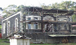
Initial heating of clear glass, using my gas torch, until it 'flowed' seemed positive, however, when I fragmented some red glass and attempted to melt the pieces back together into one, this was the result!;
It became quite evident that there were sciences involved here which were beyond my level of expertise!

Further investigations ensued and I began to look further afield. Enquiries were made OS, to the U.K. and the U.S.A. to find a source for a reasonable price. I was surprised that no Asian suppliers could be located, given the amount of other imports that are produced there. After the exchanging of many emails, I had success with an English company, Tatra glass. They were very helpful and supplied me with the 36 rondels for a shade over $200 Au, including shipping. On receipt, I was surprised to discover that they were very thin, about 2mm. All the others I had seen seemed to average about 3-4mm. I am led to believe that previously, the glass used in early English leadlights was also this thin, so it may be normal for them over there. The colouring in the glass was very dense, so if they were any thicker, they would probably have been too dark.


The downside of the deal was that very little padding was placed in the bottom of the package and 4 of the green ones, which were obviously first into the box, were shattered in transit. Their delicacy, being so thin was probably a major contributing factor.
Receiving no response from my email to the supplier in an open effort to obtain replacements, alternatives were sought. 

A couple of green bottles, pulled out of the recyclables, had there bottoms removed to see if they were suitable. As can be seen however, they seriously lacked the right look.
Trying to make best use of my time, having a couple of weeks leave, attempting to get as much of the windows finished as possible, I reached a point where I could not continue on without them. I was a bit annoyed at having to make a trip to Melbourne to find replacements.

After two ports of call and parting with $72, I returned with four more that were a little darker, but looked pretty good when viewed in the shop. They were about 70mm in diameter however, and after grinding them down to the required 50mm and fitting them in a panel, they appeared nearly black. The contrast was going to be too great with the originals, even though they were in separate panels.
A second trip was then undertaken, this time with more success. In the above photo, an original 'pommy' rondel is the third one along. The almost black appearance of the first replacements is obvious on the right. In my defence, they did have a lighter tone before the thinner perimeter was removed and the lead was wrapped around. The first one is a sample, procured during my initial searching months beforehand and the second is one of the final replacements, purchased at the same place as the sample, with the same label at $13 each. It was obviously from a different batch and was a far closer match thankfully, as the first showed more tinges of yellow. This was the reason I didn't initially source these as replacements.

As I already mentioned, I was unable to buy rondels in the sizes needed, being 40 and 50mm. All were 60+mm in diameter, so a lot of grinding was needed. It wasn't long before my fingers were suffering, cut and bleeding from holding the sharp edges, a solution was needed. After a bit of exercising of the old grey matter, the answer was the V shaped plywood holder, shown in the above picture. With angled steps cut into the inner edges it worked a treat, needing no refinements and my digits were able to heal!.

 
The 24 blue rondels, being smaller, took the most work, obviously evident with this 'before and after' photo.

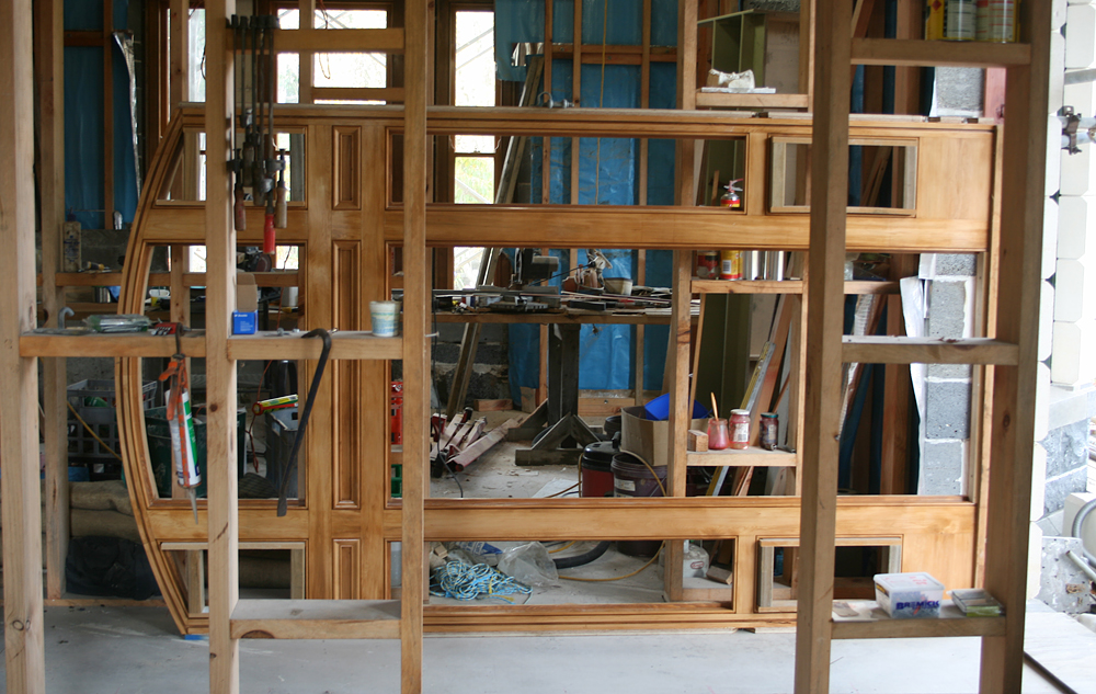
Being a bit rusty as it has been quite a number of years since my last leadlighting efforts, I thought it might be prudent to take photos of the panels prior to soldering, should I make a horrible mess of them!

The four side panels were tackled first and with them out of the way, the transom sash panel was tackled. It was intended, from the outset, that this would include the house name.
Our property sits at, what was, the back corner of a much larger farm which was owned many years ago by my Aunt and Uncle. It was accessed from Vickerys road, which was named after them, and backed onto my Grandparents farm, 'Flaxbourne'. It was purchased it when the couple were newly married. The marriage subsequently failed in the 1950's and the farm was sold, the grandparents also selling up about this time and retiring to Torquay.

Much subdividing later, the original farmhouse has long gone and I know of no photos of it. The only clues are in pictures such as this, of my Aunt and very young cousins, taken on the verandah in 1947, showing it's very rustic nature. Daffodils now annually mark the site, the only tangible evidence of it's existence.
In memory of my family's connection with the area I felt it fitting to perpetuate the name 'Claremont', the name bestowed upon the farm, prior to the time the 'Vickery's' lived there, and carried on by them.

How the name would be worked into the panel was another topic of discussion for quite some time. The length of the name and the smallness of the panel ultimately precluded it's formation in leaded form. The letters would be way too small. My favoured method was to apply it in gold leaf, which is then backed and outlined with black paint. Anita, my wife, though had other ideas. She feared that the 'blobby' look, when viewed from inside, would look terrible. That idea was then dismissed.


Scouring my photo collection, I came across this image, taken of a shopfront in Sorrento. It shows an etched panel, fitted into the leadlight panel over the doorway and we both liked and agreed on this style. The next question was how?!.
Googling the topic, I found that this sort of work was historically done using hydrofluoric acid. It is very nasty stuff and no clues were available on how to get my hands on some, so to speak!. After much more browsing, I managed to procure a couple of kits containing 'Etchall', a non acidic etching cream, very cheaply off eBay.


Once I had it, I done a few tests. It was very easy to use and the results were very sharp, although I thought the etched surface was fairly smooth and lacked real definition. For fine lettering of glassware it would be perfect, but I thought that for doing the background on a large panel it would look too soft.
For the artwork, I had done the design in my CAD program and engaged the services of a signwriter to cut out the adhesive lettering. (Thanks 
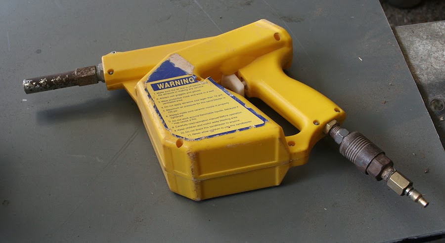
Maty, job well done!).  He questioned my method, in order to supply the correct vinyl; "was I going to sandblast it?".

That had me thinking and I remembered a cheap gun I had purchased many years ago and put away, giving it up as a bad joke. With nothing to lose, I dug it out and began playing with it. Serious problems were still evident, not being able to sustain the sand flow. As purchased, the sand was drawn up via a suction tube which I never found successful. I had cut the tube short so the gun could be inverted and the sand gravity fed. This only worked marginally better.


What had me smiling though, was that the texture it produced was eminently more suitable for my purpose. It had a much rougher, more glittery texture. This had me investigate further and I was fortunate to be able to procure some commercially supplied, proper 'blasting' sand. I found that this worked almost flawlessly in the gun. It appeared that the cause of my problems was the various self sifted sands, which I had been trying, were all too 'sharp' and they clogged in the tube. The test sample above, next to the cream etched 'A', certainly boosted my confidence. The section across the top, including horizontal line, was blasted harder, at close range to test the strength of the vinyl. It was penetrated a bit, as can be seen, and the shade of the texture around it is slightly darker.
Testing over, it was the moment of truth. I only had one 'stencil' and if I mucked it up it would be a number of days before I could get another.

To say I was happy with the result would be a gross understatement!. For continuity, the same oak leaf design, as used on the door panels, was incorporated, as can be seen.
Many people have already questioned the date selected. From my research, I have found that historically, when buildings were 'dated', the year of the physical application of the date was apparently used, as opposed to when the building was started, completed or otherwise.
The big problem now was to keep it looking this good while it was fitted into the panel!.

Sunday, January 12, 2014

78, Front Door, part 9, Painting.

In preparation for the painting and to avoid trying to mask the stone around the complex shapes, I slipped sheets of 'greaseproof' paper between the frame and the limestone. The curved 'Ovolo' moulding, to trim the head was left off and painted before it was fitted.
A coat of primer was then applied, grey behind the darker colours and white for the remainder.

With all surfaces needing at least 3 topcoats, it was a long drawn out process. The intricacy of the detail and amount of cutting in meant that I was unable to use anything larger than artists brushes for most of the work.

Difficulty in neatly priming the door with it in situ had me remove it and it spent some considerable time on stools as the details were picked out.

Unforeseen and not noticed until the second glossy topcoat, was the machining marks in the timber. Prior to painting, the wood felt silky smooth and it seemed that minimal sanding was required. Much elbow grease was expended and a lot of sandpaper was clogged, trying to rectify the problem. The above photo was taken afterwards, the corrugations in the light green, closer to and within the frieze still bearing testament to my ignorance.

In an effort to simplify the painting, I had one trial of the use of masking tape. For this purpose I purchased the best quality tape available from the local 'Bunnings' store, but as expected, from all my previous experiences with the stuff, it was a waste of effort. Despite the most meticulous care in positioning it and ensuring that the edges were firmly pressed down, much 'bleeding' still occurred. To increase the frustration, in a couple of spots, some of the underlying paint also lifted when the tape was removed. From then on, a steady, (of sorts!), hand was used for all the 'cutting in'.

The finished product, it was a huge relief to complete the last brushstrokes!.
I am very happy with the result and are in 2 minds as to whether to highlight some more detail. I had intentions of colouring the rings on the columns red, but fear it may be too much. For now I'll just leave it as is until I have completed and installed the leadlights.
The colours used are; Deep Bronze Green, Deep Indian Red, Eau De Nil, (Light Green) and Eggshell, a Haymes colour.

Sunday, September 29, 2013

77, Front Door, part 8, Modillions.

The 'Modillions', the carved brackets sitting on the capitals, supporting the 'Corona', ultimately proved to be one of the biggest sources of frustration on the project. I had left them till last, partly because they were in the 'too hard' basket and partly because they would need to be made to fit in the remaining gap.
Early in the piece, I had selected some bits of Jarrah, from which to shape them. I had cut the rough profile out on the bandsaw and had them sitting around in my way for some time, before final dimensions could be ascertained.

The plan was to emulate the foliage pattern on the originals on the 'Foynes' frame. It was quite pleasing to the eye and looked relatively easy to carve. As I was to learn, appearances can be deceiving.

I rounded up my old 'budget' set of carving chisels, which were scattered around the limestone cutting shed. The kids, before discovering computers, had been using them to shape some of my offcuts. Having been left in the open sided shed, they had grown a fair amount of surface rust, which took some work to remove, before they could be resharpened.
To say I was a bit disappointed with my initial results would be quite an understatement. After many hours of shaping and reshaping, the above picture shows the result. I could only describe it as looking like tongues, sitting on some 'pointy bits'!.
I conceded defeat and opted to get someone else, skilled in this field, to make them for me. Over the following week or so, many hours were then spent on the phone, talking to all my local contacts and clubs, attempting to find someone willing. My efforts proved futile, all the known woodcarvers in the area, bar one, were not interested in doing commission work, it was all only for hobby. The one exception, unfortunately, was on the verge of heading overseas. He was willing to assist on his return, but that was to be a couple of months away.
Much advice was also received, suggesting I search the demolition yards in an effort to locate "something suitable". This I felt would be a waste of time and didn't even bother, given the profile required and the need for them to be the correct size.
As the brackets were all that was needed to complete the frame, ready for painting, it was back to me to complete them. I was able to obtain some guidance from one of the more notable Geelong woodcarvers. His two main recommendations were; "Get some better carving timber" and "Get some better chisels"!, so these I done!.
I sourced a piece of Jelatong from which I cut the blanks and paid a visit to Carba-tec, where I parted with a couple of hundred dollars and departed with a small selection of Pfiel chisels!.

A decision was also made to individualise the carving with something a bit more recognisable. The obvious choice, given the motif on the door, was the Oak leaves. I shrank them to a suitable size and layered them sufficiently to fill the space. The inside of the cove, although lightly carved on the originals, I opted to leave plain, for reasons I'll mention in a later post!.

After much deliberation and consultation, I chose to follow on with the Oak theme and the relief carving on the sides contained a pair of acorns. More complex and detailed designs were toyed with, but I felt they would look too busy. Too much detail would be superfluous anyway, as it would tend to be flattened with the paint.

Completion of the Modillions took a quite a while to achieve. I had to force myself to find time to work on them, being rather lethargic after not being being able to farm this project out. It was a huge relief when they were done. Although being rather insignificant, they proved to be the most difficult part of the frame.
For extra insurance and piece of mind, I gave them a good soaking in some timber preservative, as Jelatong does not have a good durability rating.
With their placement, the colouring in could start!....

Sunday, August 4, 2013

76, Front Door, part 7, the Door.

To individualise the door I chose to embellish the lower panel in a similar fashion to the shamrocks on Foynes; http://www.winkieg.blogspot.com.au/2012/08/67-front-door-part-1.html.
Lots of ideas passed through my head, but my love of the Quercus genus and the slowly expanding plantation of these here for my Truffle venture, had me settle on the carving of an Oak leaf.
As we were now well into Autumn, there was plenty of leaves on the ground, from the myriad of variety's of Oak planted all around the property. I picked through the piles, collecting as diverse a range of leaf shapes as possible for a final selection.
For me, the best example that represented the Genus, that was also of pleasing proportions was the smallest one in the above photo. It belongs to Quercus Robur, the English Oak, probably the most widely planted variety in Australia, hence the familiarity. I photocopied the leaf and enlarged the image until a suitable size was attained for tracing on to the panels.
Some of the other leaves shown are a selection of American variety's, with the deeper lobes, Canary Oak, in the centre and some Mediterranean variety's, with the serrated edges.

The door was to be made entirely from Lebanese Cedar. I formed all the panels in the same way, laminating various pieces together to make up the widths and then applying bookmatched veneers to the inside faces. The bulk of the waste was then removed from the front. The edges of the raised section on the panels were routed to the finished profile with extra thickness allowed for the patterns.
Using various templates and jigs, a rough outline of the leaf shape was routed out. This ensured a flat and even background was attained. The leaf was then more finely carved to profile with chisels and the surface was veined and lightly contoured, to give it a bit more life.
The shield patterns on the upper and intermediate panels were routed using mdf templates and a bastardised rounding over bit. I couldn't locate a suitably profiled bit from the local suppliers, so the nearest alternative I could procure was carefully ground on the bench grinder, until it was close enough to the right size.

The door was assembled using the normal methods of wedged mortise and tenon joints. I ran a large quantity of bolection mouldings, more than sufficient for all of my external doors. This was owing to the amount of setup required, for the multiple passes over the router table, to achieve the desired finished profile. From memory these totalled about 7, not including the initial sizing and the final rebating. The rebates are matched to suit individual doors, dependant on the depth of the finished panel from the face.
Once completed, the hinges were sunk and the door was hung and lightly trimmed to suit the opening. The inside face was finish sanded, then, as per the frame, was also stained and lacquered before final installation.

A suitable mortice lock for the door proved rather difficult to source. Currently, the lock ranges available, incorporating a brass finish are very limited, the common response from suppliers was that it's now "out of fashion". The combination of a long case, to provide a greater visual separation of the handle from the key barrel, and the correct 'backset', left only one available option, which had to be ordered from the manufacturer in Tasmania. Unfortunately though, the supplied striker plate, the only that was available for this model, was a universal fit that looked rather flimsy and daggy with it's one long slot. Visits to a couple of restoration supplies found nothing else suitable, so I sourced some brass plate and made my own!.

The hole is finally plugged. Plywood was cut to temporarily fill the glazed openings until the leadlights are designed and made. 

The shameful self promotion couldn't be helped for this external shot, the ladder is lashed to the scaffold in that position, for access higher up!.
The only thing left to be done now, before painting, is the carved Brackets, (or Modillions), which sit above the capitals, the subject of the next post.


Monday, July 22, 2013

75, Front Door, part 6. Installation.

Monday, the 13th of May, was a bit of a highlight for me. The frame was finally ready to be installed. All the loose bits were taken off and put aside, then, with the aid of a number of ropes and shackles, I lifted  it off the stools and dropped one side to the floor.

Resting on the reveal, I was then able to slide the unit through to the entry, where, using the ropes again, I lowered it flat to the floor. The temporary frames were left in the corner sash openings to help avoid any damage.

With the bottom positioned on the cill, I reattached ropes to the head and via shackles, fed it up to the rafters and back down to within easy reach. I was able to lift it up in stages by hand, holding it, after each grunt, by the rope. Owing to imperfections in the hand hewn bluestone cill, which I felt would be too hard to copy to the timberwork via measurements or templates, I opted to leave the frame slightly oversize and mark scribe lines on it, once in position. This, thankfully, worked satisfactorily the first time and I only needed to lower it back down once for trimming.

I was more than happy with the fit, just like the proverbial glove. The sides were screwed, through the reveals, into trimmers bolted to the stonework.

The stone cill already had holes sunk into it from it's previous life and I was careful to make sure that the mullions would cover them when designing the frame.

Grooves were chiseled in the base of the frame and the pedestal backing block to accommodate a stainless steel bolt. The bolt was then epoxied in place, sandwiched between the timbers with the head located into the rearmost hole.

With the frame all secured in place, the sashes were trimmed and fitted and a start was made on the attaching of the appendages.
First up, the pedestals were boxed out and capped. The Lebanese cedar that I used for these and the upper portions of the plinth, came from a tree removed From Kardinia park in Geelong. The poorer, slower growing conditions there, other than that at Daylesford, from where the rest of my supply originated, created a tighter more attractive figure in the timber. The difference is quite apparent in the above photo, where a comparison can be made with the infill panel. For the lower, larger portion of the plinth, I used Celery top pine, which, being much more dense, should cope better with any knocking or scuffing.
During assembly, I am placing the "grease proof" paper behind the timber, to avoid getting paint all over the stonework. Hopefully it can simply and cleanly be pulled out later.

Sunday, May 12, 2013

74, Front Door, part 5. Corinthian capitals.

Concurrently with the turning of the columns, much work progressed on the making of the Corinthian capitals to crown them. Ultimately it took many more hours to produce these relatively small features, than the making of the columns themselves.
For the patterns, I had sourced some original odd metal pieces of suitable verandah post capitals from a local house wrecker, one full quarter and a couple of half quarters. As procured, they were relatively plain, having been coated with a thick layer of some sort of putty and numerous coats of paint.

The first step was to remove the coatings. A handy bit of advice had me cooking it on the stove, in a pot of boiling water with a bit of bicarbonate of soda added. It worked a treat, with the layers literally falling off.

The full piece was scrubbed completely clean and mounted in a rough box, then casting plaster was poured around it to fill the voids. A remeltable rubber was then used to make a mould. The product, sold locally as "Gelflex", works out at close to the same price as conventional 2 part silicone rubber, but being reusable works out far cheaper in the long run.


From the rubber mould, (it took a couple of go's to get that right), I cast an oversize model, to give me more width at the bottom. The original pieces were of the desired proportions at the top, however, they were a little too high for my purpose and they were made to fit around a 75mm, (3 inch), post. My columns were 90mm diameter.
The hours ticked by as I reshaped and carved the plaster model to achieve the result shown on the left. I wasn't entirely happy with the shape that I ended up with, as it tended to flare back outwards at the bottom, creating a narrow neck. I was loathe to redo it, given the time spent. Ultimately though, I was unsuccessful in attempting to mould it. I had coated it with various different products, including silicon spray, to seal the plaster to prevent air escaping into and bubbling the hot rubber. This was all to the detriment of the model and I started over again, producing the second one, on the right with the more pleasing profile.
The bottom section on the models was also made a little wider to avoid having to piece in small fillets at the rear, where the 'not required' fourth piece would have fitted, against the mullion.
My attempts to mould the second model were also not without problems. Much google searching had a supplier of of a similar product, "Flexil",recommending sealing the plaster with a number of coats of diluted PVA glue. This was the only advice I was able to locate, other than "the plaster must be sealed"!. They also recommended providing ventilation holes below the unsealed base of the model. I tried this to no avail, having worse results than before with the rubber bubbling excessively and setting like a sponge. At that point I could see the only solution to be to coat it with a thin layer of epoxy and sealing it to the baseboard. This did prove satisfactory, however, around the sides, where I had applied the coating a lot thicker, the heat softened the layer, causing it to blister. Fortunately, the face moulded well and I was able to get on with casting the finished product.

For the ten pieces I required, I cast them using an epoxy resin; nuplexcomposites Epoxy R180. In order to reduce the amount of resin used, and therefore reduce the cost, this was bulked out, to over twice it's volume, with the addition of hollow glass spheres. These also lightened the weight and gave them the white colour.
I gave them a couple of days to harden sufficiently before trimming the mitres and gluing them together. Once assembled, the backs were cut roughly to shape and the capitals were clamped down as seen in the picture. To reduce wastage, all the offcuts were reused, hacked into smaller pieces and placed in the centres with more epoxy mixed to fill the voids. As I looked at this scene before taking the photo, I realised how stupid I was with the risk I was taking, with this being carried out on a board sitting on the completed frame. Should a clamp slip or fail, I would have a hell of a mess oozing all over the finished work!.

Leaving the castings to fully harden, I turned my attention to the arris mouldings. The positions of these could now be marked out, corresponding with the profiles of the columns. Routing the ovolo shape was the easy part, Carving the bevelled chamfers at the ends, however, tested my patience. I had considered a "lambs tongue" profile for these, but on a sample test piece the plain bevel proved to be difficult enough, maintaining the flat plane around the ovolo curve. I tried grinding the cutting edge of a chisel into a curve to trim the convex shape into the transition point, but found that I was able to achieve better results using a plain flat chisel instead.

For smoothing the ends of the ovolo, I whipped up a couple of small sanders. The first, I made using sections of plastic conduit, laminated together and attached to a handle. The lower most section had the sandpaper glued to it, pressed in place using some dowel, before it was glued to the remainder. With this needing some time to dry, owing to the solvent based glue used, I whipped up a second one. This time, I used a short length of scotia moulding, fixed to a handle before having the sandpaper glued on. The ends of both were roughly curved to the correct shape with an angle grinder, the only thing I could think of that would not be damaged by the silicone carbide abrasive paper I had used.

With all the major components ready to go, I screwed and glued lengths of 18mm marine ply "reveals" to the two sides. These would give me something to fix through to secure the frame to the jambs. The dentils were made up in a long strip from thin marine ply, being a 'T' shape in vertical section. They were then docked off in 25mm widths and glued and tacked in position. The capitals were then trimmed up and sanded and a final dry assembly was made, to see how it all looked.
Still to be done, apart from the pedestal caps and bases, are the carved modillions, that sit on top of the capitals. These will be tackled after installation of the frame, when more accurate dimensions can be measured.