Concurrently with the turning of the columns, much work progressed on the making of the Corinthian capitals to crown them. Ultimately it took many more hours to produce these relatively small features, than the making of the columns themselves.
For the patterns, I had sourced some original odd metal pieces of suitable verandah post capitals from a local house wrecker, one full quarter and a couple of half quarters. As procured, they were relatively plain, having been coated with a thick layer of some sort of putty and numerous coats of paint.
The first step was to remove the coatings. A handy bit of advice had me cooking it on the stove, in a pot of boiling water with a bit of bicarbonate of soda added. It worked a treat, with the layers literally falling off.
The full piece was scrubbed completely clean and mounted in a rough box, then casting plaster was poured around it to fill the voids. A remeltable rubber was then used to make a mould. The product, sold locally as "Gelflex", works out at close to the same price as conventional 2 part silicone rubber, but being reusable works out far cheaper in the long run.
From the rubber mould, (it took a couple of go's to get that right), I cast an oversize model, to give me more width at the bottom. The original pieces were of the desired proportions at the top, however, they were a little too high for my purpose and they were made to fit around a 75mm, (3 inch), post. My columns were 90mm diameter.
The hours ticked by as I reshaped and carved the plaster model to achieve the result shown on the left. I wasn't entirely happy with the shape that I ended up with, as it tended to flare back outwards at the bottom, creating a narrow neck. I was loathe to redo it, given the time spent. Ultimately though, I was unsuccessful in attempting to mould it. I had coated it with various different products, including silicon spray, to seal the plaster to prevent air escaping into and bubbling the hot rubber. This was all to the detriment of the model and I started over again, producing the second one, on the right with the more pleasing profile.
The bottom section on the models was also made a little wider to avoid having to piece in small fillets at the rear, where the 'not required' fourth piece would have fitted, against the mullion.
My attempts to mould the second model were also not without problems. Much google searching had a supplier of of a similar product, "Flexil",recommending sealing the plaster with a number of coats of diluted PVA
glue. This was the only advice I was able to locate, other than "the plaster must be sealed"!. They also recommended providing ventilation holes below the unsealed base of the model. I tried this to no avail, having worse results than before with the rubber bubbling excessively and setting like a sponge. At that point I could see the only solution to be to coat it with a thin layer of epoxy and sealing it to the baseboard. This did prove
satisfactory, however, around the sides, where I had applied the coating a lot thicker, the heat softened the layer, causing it to blister. Fortunately, the face moulded well and I was able to get on with casting
the finished product.
For the ten pieces I required, I cast them using an epoxy resin;
nuplexcomposites Epoxy R180. In order to reduce the amount of resin used, and therefore reduce the cost, this was bulked out, to over twice it's volume, with the addition of
hollow glass spheres. These also lightened the weight and gave them the white colour.
I gave them a couple of days to harden sufficiently before trimming the mitres and gluing them together. Once assembled, the backs were cut roughly to shape and the capitals were clamped down as seen in the picture. To reduce wastage, all the offcuts were reused, hacked into smaller pieces and placed in the centres with more epoxy mixed to fill the voids. As I looked at this scene before taking the photo, I realised how stupid I was with the risk I was taking, with this being carried out on a board sitting on the completed frame. Should a clamp slip or fail, I would have a hell of a mess oozing all over the finished work!.

Leaving the castings to fully harden, I turned my attention to the arris mouldings. The positions of these could now be marked out, corresponding with the profiles of the columns. Routing the ovolo shape was the easy part, Carving the bevelled chamfers at the ends, however, tested my patience. I had considered a "lambs tongue" profile for these, but on a sample test piece the plain bevel proved to be difficult enough, maintaining the flat plane around the ovolo curve. I tried grinding the cutting edge of a chisel into a curve to trim the convex shape into the transition point, but found that I was able to achieve better results using a plain flat chisel instead.

For smoothing the ends of the ovolo, I whipped up a couple of small sanders. The first, I made using sections of plastic conduit, laminated together and attached to a handle. The lower most section had the sandpaper glued to it, pressed in place using some dowel, before it was glued to the remainder. With this needing some time to dry, owing to the solvent based glue used, I whipped up a second one. This time, I used a short length of scotia moulding, fixed to a handle before having the sandpaper glued on. The ends of both were roughly curved to the correct shape with an angle grinder, the only thing I could think of that would not be damaged by the silicone carbide abrasive paper I had used.

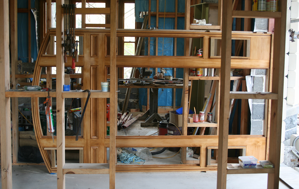
With all the major components ready to go, I screwed and glued lengths of 18mm marine ply "reveals" to the two sides. These would give me something to fix through to secure the frame to the jambs. The dentils were made up in a long strip from thin marine ply, being a 'T' shape in vertical section. They were then docked off in 25mm widths and glued and tacked in position. The capitals were then trimmed up and sanded and a final dry assembly was made, to see how it all looked.
Still to be done, apart from the pedestal caps and bases, are the carved modillions, that sit on top of the capitals. These will be tackled after installation of the frame, when more accurate dimensions can be measured.