By May the sashes had been trimmed to fit, sanded and grooved down about 2/3rd's of their sides for the ropes. They were now ready to be painted, just in time for an early onset of a cold and wet Winter!.
For the remainder of this stage, the downstairs windows were to be completed and installed first before I would tackle the rest.
Prior to final assembly, I coated the internal faces of the sashes with a light stain, to darken the timber slightly and reduce the contrast with the Blackwood linings. This was followed by 2 coats of polyurethane. The outsides were primed and then given one coat of gloss enamel, also sealing the glazing rebate. To save my limited space, I knocked up a drying rack, in which I could place 12 sashes at a time. The cold and damp delayed the process and each coat was taking up to a frustrating 3 days to dry.
The Frames were also given a similar treatment and spread around all the available floor space. During my working stints in the workshop, I used a gas patio heater to warm the air to help the drying but, due to the fire hazard, I wasn't game to leave it on when not present. With an 8.5kg gas bottle only lasting up to 3 days anyway, it wasn't proving to be too economical!.
During this time, my research into the different methods of double glazing never waned. After much deliberation I settled on a product called SuperSpacer. The main advantage with this, in my situation, was that was available in a narrow 4.8mm, this would enable the panels to be kept to a minimal thickness of about 13mm. If the air space was made any wider, even though efficiency would dramatically increase, the units would not fit in the frames.
The spacers, reasonably priced at around $2 per metre, are a flexible, desiccant impregnated, pre glued strip. They require some sort of application jig to maintain a uniform margin and straight lines. I travelled across Melbourne to the helpful suppliers, C.R.Laurence, and purchased 4, twenty metre rolls as well as a sufficient quantity of the secondary sealant. A small plastic "Hand notcher", used for the spacers placement was priced at about $230, but was not suitable for the narrow 4.8mm strip. A close inspection of one showed that it would be possible to be modified, but I figured, for the price, I could make my own. The "Hand notcher" was also designed to provide a 4.8mm set back from the edge of the glass, required by the manufactures specs., for the secondary sealant. To reduce the sight line in my sashes, which have a 1/4", (6.35mm), wide rebate I would also need to reduce the setback.
I fashioned my home made applicator from a scrap block of Celery Top Pine. It included a sprung plastic roller, to firmly press the spacer to the glass. I initially made it to provide a 1mm setback, as it could later be shaved to increase this. It worked extremely well and I had intentions of adding a plunge action punch for notching the corners. This would be added after any other fine tuning that was required.
I made a couple of trial units to get a feel of the process and assess the results. It was surprisingly easy to do, but with only one pair of hands it was quite difficult to hold the glass steady, work the applicator and feed in the spacer, which needed the plastic tape removed in advance to expose the adhesive. This led to the spacer drifting at one point when it stuck to the glass ahead of me. 1st negative!. Being a trial, I opted to leave it as is, to see how unsightly it would look.
Once I had fitted a trial unit, my fears were confirmed. Even with the minimal setback, the grey spacer was quite pronounced and detracted from the overall look. 2nd negative!.
On the upper left stile on this sash can be seen where the spacer drifted, not looking too good!. It also demonstrated how much grey would be seen with a more suitable setback, way too much.
I assembled the second trial unit to temporarily replace a broken pane in a bay window in our existing Lounge, the result seems to be somewhat disappointing. On the coldest nights, with the wood stove raging to warm the room as much as possible, there was no discernible differences to the glass temperatures, between this unit and the single panes, inside or out. No doubt, with sophisticated measuring instruments, there would be variances, but would it be worth the effort?, 3rd negative!
Using the 4mm glass that I already had, I found that, although the panels fitted neatly into the sashes, the remaining rebate of 3 to 4mm was too small to be able to accommodate a nailed beading, the rebates on all the sashes would need to be deepened by an additional 3mm for a neat external finish, 4th negative!.
For many years I had been accumulating cast iron window weights from many sources, so long as they were cheap, or free!. My collection received a huge boost, about 10 years back, when I was able to intercept about 84 of them, destined for scrap. I have no idea as to their origin, they were all between 12 and 14 lbs each, (roughly 5.5 to 6.3kg), and I hadn't seen any of this size before. The largest, from the rest of my collection, was 10 lbs, with the average being about 7 to 8. The owner estimated their scrap value to be about $40 and had me part with that for their exchange, not bad for half a ton of iron. I had the notion that these would be more than ample for the increased weight due to double glazing, wrong!.
With the trials made, I was able to start measuring the weights of the glass and sash's to get an idea of the counterbalance requirements. I nearly fell over when the scales told me that I was looking at an average weight of about 40 lb's per sash!, that would require a 20 lb weight each side.
I had designed the hidden pockets, in the pulley stiles, to be larger than normal to allow the insertion of my largest available weight, being 14 lb's and about 650mm in length. With cast iron, there would be no way of fitting 20 lb slugs, even if I could find any. Calculations were made and I concluded that the only way that it would be possible, would be to cast them, in a square profile, out of Lead. This was a path I wasn't too keen in taking, as if I didn't have enough on my plate already!, 5th negative.
The negatives were adding up and at this point, I had yet to find a positive!. I felt that I had given it every opportunity to prove it worthwhile and figured that enough time had already been wasted, so, Double Glazing was out!
The 4mm thick glass also made a large difference to the weight, most early windows that I have seen used only 3mm thick stuff. Even with single glazing, the 14 lb weights were only just going to be suitable for my largest sash's, the average would be about 11 lbs.
Sunday, June 24, 2012
Monday, April 30, 2012
63, Back pedal! Enough stone.
A couple of years back, I noticed, during my travels, a large collection of basalt rocks being uprooted from the ground and formed into piles on a property south east of Winchelsea. A closer inspection revealed that a large proportion of the stone was very clean with a fine grain. It appeared that it would be satisfactory for my steps, paving, verandah edging and anything else for which the honeycomb stuff wasn't suitable. The best part was that was only 20 minutes from home, at one of the nearest volcanic eruption points.
Following brief negotiations with the owner, I was given permission to remove as much as I liked, (with his preference being the largest ones!), in exchange for my cutting him "a couple of steps".
The collection of this stone was put on the backburner until recently, with many issues delaying the
procurement. If the truck was not out of action, the ground was too boggy or I was busy on something else etc. The latest hiccup in the saga was the death of the motor in the front end loader. It died about a year ago and the machine still rests, to this day, where it stopped, next door, waiting for a promised diagnosis from a diesel mechanic.
I had intentions of amassing enough of this stone, along with some more honeycomb stuff, to ensure that there would be plenty to finish my house with. We would then be able to dispose of the truck, it was costing nearly $1,500 a year for it to stay registered while spending most of it's time sitting in the yard. I had also booked some long service leave from work, to be taken in early December, 2011, with the aim of achieving this, hopefully in dry weather, before the truck rego was due in February.
With the loader out of action and not wanting to delay the collecting any longer, should the owners situation or mood change, I opted to take my generator and tools on site. There, I would split the rocks into manageable, usable sizes that could be transported home in the trailer.
The longest stone steps needed were to be about 1800mm long, (6ft), so that was my initial aim and started work on the largest of the rocks. I found that the stone was quite hard, more difficult than what I had previously encountered and my first attempts at drilling these proved futile. I then moved to the smaller one above, which was about 8ft long by about 4ft.
The drilling was a little easier on this stone and it furnished me with pieces long enough for 2 steps. The lump that fell off the near end was due to an inherent crack. This sort of thing, as frustrating as it is, is a good side effect of splitting the stone rather than sawing it. Defects, such as this, are identified before too much work is done.
After the first day, I'm loaded and stuffed!. The near piece on the trailer was the smaller one, to the left in the upper photo's and weighed over a tonne, more than the limit for my block and tackle. The other two were were split from other rocks. The day was a long one and got off to a bad start when the generator refused to fire, despite having been tested the night before. A visit to a mechanic in Winchelsea had a faulty spark plug diagnosed and replaced. My hands became very blistered from the endless chain, when winching the pieces out of the pile to clear ground, (about 6 meters), and then into the trailer.
I managed to split a number of stones ready for loading, however some, such as the remaining piece from the previously mentioned one and another, of which the edge could just be seen to the left in the above photo, were going to be far too heavy for my equipment. If I attempted to split them further, I risked the possibility of them breaking across the shorter axis and rendering them useless. Loading by hand clearly wasn't going to be feasible.
Inquiries were made and the original contractor who had removed the rocks was contacted. He offered, for $100 a load, to send one of his blokes over with an excavator to lift them into the truck. With the offer accepted, I was back two days later with the truck. The first load included the bits that I had already split. One of these, the lump being loaded in the above pic, weighing about 3 tonnes, tested the machines capability and it struggled to lift it to this height without overbalancing. A couple of slightly larger ones were also tackled, but, for those we fashioned a ramp over a pile of rubble and drove them in.
The loading cost was well justified, with the more than helpful operator extracting the better rocks, previously marked by me, from the amidst the piles, while I was unloading the truck.
Four or Five loads were obtained, (my memory is failing me now), and I called it quits when we had taken the most promising looking stuff and I reckoned that I had sufficient for my purposes.. There was more stone accessible, but, the sizes were reducing. Unfortunately, when they were originally being dug out, many were split into smaller chunks for possible future processing. Larger rocks were still available, but they were becoming harder to extract, being buried far too deeply in the heap.
The stockpile at home, with the larger stuff over to the left and the first obtained lumps behind the trailer, on the right.
Also on the agenda for my leave was the collection of two loads of large flat slabs from a quarry at Ondit, near the northern shore of Lake Colac.When originally searching for a source of building stone, I had visited this quarry and although they had some suitable material, I dismissed it as being way too expensive. I figure that I now have close to enough good face stone to complete my house, however, my supply of material suitable for the cutting of "tie" stones was waning. These blocks needed a front to back dimension of at least 415mm, being the thickness of the wall masonry.
A year or so back I re approached the quarry operator and requested that any suitable slabs be kept aside. As the pit is expanded the upper crustal layer of vesicular basalt, (honeycomb), is removed to extract the finer grained material below. This surface layer often produces large, flat, parallelled surfaced evenly textured rock. Being from the same lava flows and located only a short distance from Warrion, where I had sourced my original stone, the color and appearance matched.
When I arrived there, during the week following the stone collection from Winchelsea, I found that the quarry operators had collected more than enough for me and stored them in a disused part of the workings. This was great, it allowed me to select the best of the best!. The hiccup was that the quarry were not happy to load the stone, having only front end loaders they would only load from the rear through the open tailgate, limiting the amount they could put in to 1 or 2 slabs. They did, however, put me in contact with a local contractor who operated a large forklift. Large?, it was massive with a 26 tonne capacity, capable of lifting the fully laden truck!. As can be seen in the above photo, a 2 tonne slab looked pretty insignificant, sitting on the forks.
The exercise didn't come cheap with the stone, at nearly $30 a tonne, costing over $600 for the 2 loads. The loading proved quite fiddly and time consuming with the limited maneuverability of the forks and set me back a further $150, at least I didn't have to also find cash to pay for transport costs.
The largest slab, taken in the first load and seen on the bottom, to the right of the truck in the above photo, was estimated at about 4 tonnes. The one on top is about 3 tonnes and the other 3 from that load were about 1 tonne each, the total load being just over 10 tonnes.
I should now have more than enough raw material for the house and can now channel more energy into actually putting it together!. For the remaining two weeks of my leave, my attention was diverted back to the rebuilding of my sanding machine.
Following brief negotiations with the owner, I was given permission to remove as much as I liked, (with his preference being the largest ones!), in exchange for my cutting him "a couple of steps".
The collection of this stone was put on the backburner until recently, with many issues delaying the
procurement. If the truck was not out of action, the ground was too boggy or I was busy on something else etc. The latest hiccup in the saga was the death of the motor in the front end loader. It died about a year ago and the machine still rests, to this day, where it stopped, next door, waiting for a promised diagnosis from a diesel mechanic.
I had intentions of amassing enough of this stone, along with some more honeycomb stuff, to ensure that there would be plenty to finish my house with. We would then be able to dispose of the truck, it was costing nearly $1,500 a year for it to stay registered while spending most of it's time sitting in the yard. I had also booked some long service leave from work, to be taken in early December, 2011, with the aim of achieving this, hopefully in dry weather, before the truck rego was due in February.
With the loader out of action and not wanting to delay the collecting any longer, should the owners situation or mood change, I opted to take my generator and tools on site. There, I would split the rocks into manageable, usable sizes that could be transported home in the trailer.
The longest stone steps needed were to be about 1800mm long, (6ft), so that was my initial aim and started work on the largest of the rocks. I found that the stone was quite hard, more difficult than what I had previously encountered and my first attempts at drilling these proved futile. I then moved to the smaller one above, which was about 8ft long by about 4ft.
The drilling was a little easier on this stone and it furnished me with pieces long enough for 2 steps. The lump that fell off the near end was due to an inherent crack. This sort of thing, as frustrating as it is, is a good side effect of splitting the stone rather than sawing it. Defects, such as this, are identified before too much work is done.
After the first day, I'm loaded and stuffed!. The near piece on the trailer was the smaller one, to the left in the upper photo's and weighed over a tonne, more than the limit for my block and tackle. The other two were were split from other rocks. The day was a long one and got off to a bad start when the generator refused to fire, despite having been tested the night before. A visit to a mechanic in Winchelsea had a faulty spark plug diagnosed and replaced. My hands became very blistered from the endless chain, when winching the pieces out of the pile to clear ground, (about 6 meters), and then into the trailer.
I managed to split a number of stones ready for loading, however some, such as the remaining piece from the previously mentioned one and another, of which the edge could just be seen to the left in the above photo, were going to be far too heavy for my equipment. If I attempted to split them further, I risked the possibility of them breaking across the shorter axis and rendering them useless. Loading by hand clearly wasn't going to be feasible.
Inquiries were made and the original contractor who had removed the rocks was contacted. He offered, for $100 a load, to send one of his blokes over with an excavator to lift them into the truck. With the offer accepted, I was back two days later with the truck. The first load included the bits that I had already split. One of these, the lump being loaded in the above pic, weighing about 3 tonnes, tested the machines capability and it struggled to lift it to this height without overbalancing. A couple of slightly larger ones were also tackled, but, for those we fashioned a ramp over a pile of rubble and drove them in.
The loading cost was well justified, with the more than helpful operator extracting the better rocks, previously marked by me, from the amidst the piles, while I was unloading the truck.
Four or Five loads were obtained, (my memory is failing me now), and I called it quits when we had taken the most promising looking stuff and I reckoned that I had sufficient for my purposes.. There was more stone accessible, but, the sizes were reducing. Unfortunately, when they were originally being dug out, many were split into smaller chunks for possible future processing. Larger rocks were still available, but they were becoming harder to extract, being buried far too deeply in the heap.
The stockpile at home, with the larger stuff over to the left and the first obtained lumps behind the trailer, on the right.
Also on the agenda for my leave was the collection of two loads of large flat slabs from a quarry at Ondit, near the northern shore of Lake Colac.When originally searching for a source of building stone, I had visited this quarry and although they had some suitable material, I dismissed it as being way too expensive. I figure that I now have close to enough good face stone to complete my house, however, my supply of material suitable for the cutting of "tie" stones was waning. These blocks needed a front to back dimension of at least 415mm, being the thickness of the wall masonry.
A year or so back I re approached the quarry operator and requested that any suitable slabs be kept aside. As the pit is expanded the upper crustal layer of vesicular basalt, (honeycomb), is removed to extract the finer grained material below. This surface layer often produces large, flat, parallelled surfaced evenly textured rock. Being from the same lava flows and located only a short distance from Warrion, where I had sourced my original stone, the color and appearance matched.
When I arrived there, during the week following the stone collection from Winchelsea, I found that the quarry operators had collected more than enough for me and stored them in a disused part of the workings. This was great, it allowed me to select the best of the best!. The hiccup was that the quarry were not happy to load the stone, having only front end loaders they would only load from the rear through the open tailgate, limiting the amount they could put in to 1 or 2 slabs. They did, however, put me in contact with a local contractor who operated a large forklift. Large?, it was massive with a 26 tonne capacity, capable of lifting the fully laden truck!. As can be seen in the above photo, a 2 tonne slab looked pretty insignificant, sitting on the forks.
The exercise didn't come cheap with the stone, at nearly $30 a tonne, costing over $600 for the 2 loads. The loading proved quite fiddly and time consuming with the limited maneuverability of the forks and set me back a further $150, at least I didn't have to also find cash to pay for transport costs.
The largest slab, taken in the first load and seen on the bottom, to the right of the truck in the above photo, was estimated at about 4 tonnes. The one on top is about 3 tonnes and the other 3 from that load were about 1 tonne each, the total load being just over 10 tonnes.
I should now have more than enough raw material for the house and can now channel more energy into actually putting it together!. For the remaining two weeks of my leave, my attention was diverted back to the rebuilding of my sanding machine.
Saturday, April 28, 2012
62, Sash assembly.
One detail, previously not mentioned, is the beading I had run on inside faces of the sash pieces. When I built my initial cottage, seen here in the beginning, It was designed and built around the 2 front windows. These I had rescued from one of the last remaining, original cottages in Torquay. Sited on the main Geelong road, it was being demolished to make way for the exploding surf industry. You can't stop progress, but it was all I could do at the time to preserve the past. The wood stove from the kitchen was claimed as well, but unfortunately, the chimney came down, rather quicker than was expected, and reduced it to scrap.
The beading's on these windows are the standard Victorian profile with the size matching the glazing rebate of 1/2" x 1/4", (12.7mm x 6.4mm). The curve segment is less than 1/4, giving it a flattened appearance. The balance of the windows in my cottage were a combination of some crappy recycled hardwood frames and 3 other sets I made myself, my first foray into this area. For these I purchased "off the shelf" moulded cedar, (western red), stiles and rails, although the beading moulding was different. I was happy with the results and the kitchen window is still working beautifully, the other two were removed to make way for the "extension". The construction of these gave me the confidence to completely make, from scratch, a new Bay window, shortly before I commenced the extension. This was to replace the large, rotting hardwood frame that I had installed in the west wall. This time I made some effort to replicate the original beading's using a small, 1/4 segment, concave router bit. I tweaked the stepped shoulders to get the nearest visual likeness that I could. This worked reasonably well, but, when it came to the windows for the main house, my standards were improving and near enough wouldn't be good enough!. For these I bit the bullet and ordered a new router bit, custom profiled. During my travels I had managed to procure an old wooden hand moulding plane with the correct blade for doing these, however, my enthusiasm for the construction did not quite stretch far enough to go down that path!.
Having all the main pieces machined, things became more hands on and fiddlier. The faces of all the stiles, at the base of the horns, adjacent to where the meeting rails join, had to made flush with the rebate and sanded smooth. The beading on the lower stiles was shaved back and scribed, however, on the upper stiles it was cut flush as, on these, there is no bead on the meeting rail.
The opposite ends of the stiles required rebates to be formed to accommodate the haunched tenons, this prevents the top and bottom rails from twisting. Then the beading's were also cut back and scribed.
A test fit of a meeting rail and a stile for a bottom sash. On the lower sashes, the glass fits up into a groove in the meeting rail .
No shed is ever big enough!. I could only scrounge enough room to set up two gluing tables and with the exception of the narrow sidelights, shown in the upper photo, I was only able to set up enough clamping for four sashes at a time. This worked out to be sufficient anyhow, as it was taking anything up to an hour to prepare each sash, this included the previously mentioned trimming and the fine tuning of the shoulders and scribes to true up the joints. I struggled to keep up, having enough sashes prepared for when the glue on the previous lot had set.
For 6 days straight, I had 2 clamping sessions per day, one about midday and the other about midnight. These sessions took about 2 hours each, by the time I coated the glued surfaces, assembled the sashes, lightly clamped and squared them, tapped the wedges firm, hammered in the joint wedges and then wiped all the excess glue from the faces.
I do possess an odd collection of sash clamps, but, when set up for this sort of work they tend to be unwieldy and hard to control. With their average lengths being about 1800mm, (6 ft), they would also require a lot more space. For this project I opted to assemble simple clamping jigs using wedges. The back blocks, being screwed down, could be easily relocated to suit the differing widths. I hadn't tried clamping this way before but was very happy with the method, it was very simple and effective.
By the last night, I was buggered, but was certainly glad to have had this bit over with.
At last, the sashes are together, all ready for trimming and sanding. They all look good, bar one. In my haste, (or stupor), to clamp up the final batch, I was careless with one joint, then over clamped it to close the gap, which led to it twisting. Fortunately though, it was for one of 2 sidelight windows which are fixed in place.
This simple jig, set up on my bandsaw, allowed me to quickly and neatly trim the waste from the wedges and tenons.
The joints are trimmed and the sashes are ready for sanding, before the trimming of the stiles, bevelling of the bottom of the lower sash's, grooving the sides for the ropes and fitting into the frames. There's still a long way to go....
The beading's on these windows are the standard Victorian profile with the size matching the glazing rebate of 1/2" x 1/4", (12.7mm x 6.4mm). The curve segment is less than 1/4, giving it a flattened appearance. The balance of the windows in my cottage were a combination of some crappy recycled hardwood frames and 3 other sets I made myself, my first foray into this area. For these I purchased "off the shelf" moulded cedar, (western red), stiles and rails, although the beading moulding was different. I was happy with the results and the kitchen window is still working beautifully, the other two were removed to make way for the "extension". The construction of these gave me the confidence to completely make, from scratch, a new Bay window, shortly before I commenced the extension. This was to replace the large, rotting hardwood frame that I had installed in the west wall. This time I made some effort to replicate the original beading's using a small, 1/4 segment, concave router bit. I tweaked the stepped shoulders to get the nearest visual likeness that I could. This worked reasonably well, but, when it came to the windows for the main house, my standards were improving and near enough wouldn't be good enough!. For these I bit the bullet and ordered a new router bit, custom profiled. During my travels I had managed to procure an old wooden hand moulding plane with the correct blade for doing these, however, my enthusiasm for the construction did not quite stretch far enough to go down that path!.
Having all the main pieces machined, things became more hands on and fiddlier. The faces of all the stiles, at the base of the horns, adjacent to where the meeting rails join, had to made flush with the rebate and sanded smooth. The beading on the lower stiles was shaved back and scribed, however, on the upper stiles it was cut flush as, on these, there is no bead on the meeting rail.
The opposite ends of the stiles required rebates to be formed to accommodate the haunched tenons, this prevents the top and bottom rails from twisting. Then the beading's were also cut back and scribed.
A test fit of a meeting rail and a stile for a bottom sash. On the lower sashes, the glass fits up into a groove in the meeting rail .
No shed is ever big enough!. I could only scrounge enough room to set up two gluing tables and with the exception of the narrow sidelights, shown in the upper photo, I was only able to set up enough clamping for four sashes at a time. This worked out to be sufficient anyhow, as it was taking anything up to an hour to prepare each sash, this included the previously mentioned trimming and the fine tuning of the shoulders and scribes to true up the joints. I struggled to keep up, having enough sashes prepared for when the glue on the previous lot had set.
For 6 days straight, I had 2 clamping sessions per day, one about midday and the other about midnight. These sessions took about 2 hours each, by the time I coated the glued surfaces, assembled the sashes, lightly clamped and squared them, tapped the wedges firm, hammered in the joint wedges and then wiped all the excess glue from the faces.
I do possess an odd collection of sash clamps, but, when set up for this sort of work they tend to be unwieldy and hard to control. With their average lengths being about 1800mm, (6 ft), they would also require a lot more space. For this project I opted to assemble simple clamping jigs using wedges. The back blocks, being screwed down, could be easily relocated to suit the differing widths. I hadn't tried clamping this way before but was very happy with the method, it was very simple and effective.
By the last night, I was buggered, but was certainly glad to have had this bit over with.
At last, the sashes are together, all ready for trimming and sanding. They all look good, bar one. In my haste, (or stupor), to clamp up the final batch, I was careless with one joint, then over clamped it to close the gap, which led to it twisting. Fortunately though, it was for one of 2 sidelight windows which are fixed in place.
This simple jig, set up on my bandsaw, allowed me to quickly and neatly trim the waste from the wedges and tenons.
The joints are trimmed and the sashes are ready for sanding, before the trimming of the stiles, bevelling of the bottom of the lower sash's, grooving the sides for the ropes and fitting into the frames. There's still a long way to go....
Thursday, April 19, 2012
61, Joinery, part four, Window sash preparation.
The tedium of assembly line work has reached new levels with the commencement of the sash construction. 23 window frames equals 46 sashes equals 92 stiles and 92 rails equals 184 wedged, mortise and tenon joints!
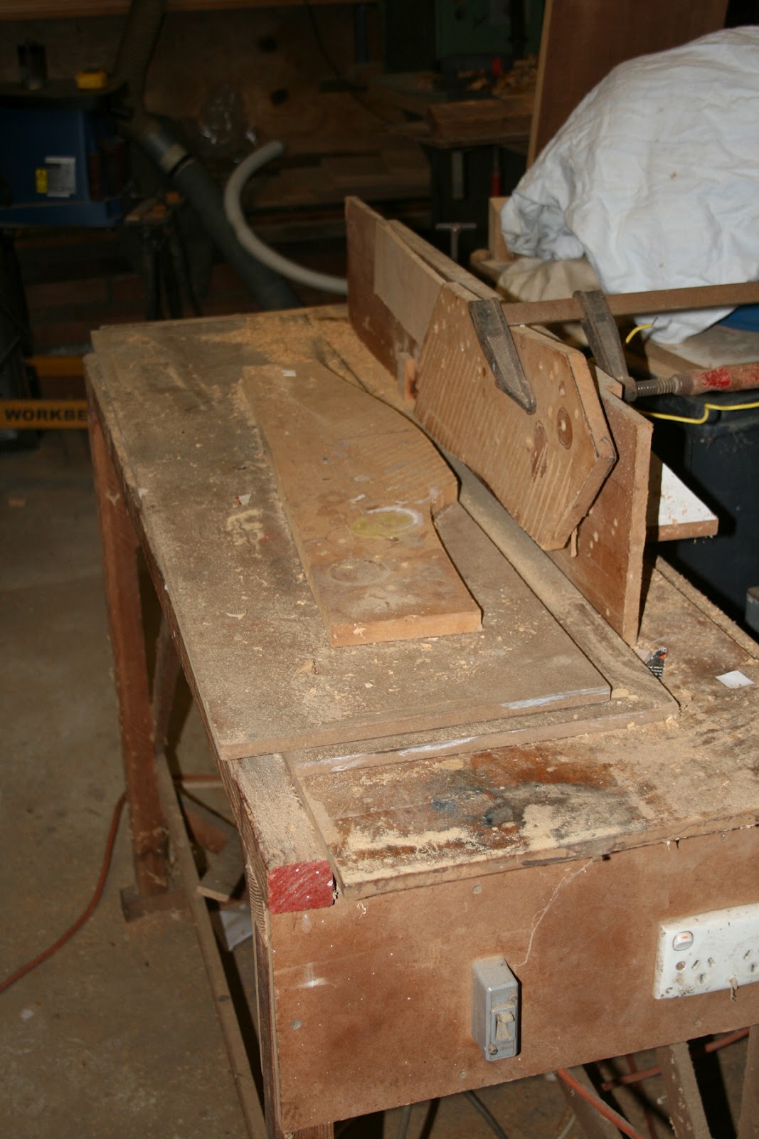
The mouldings and rebates I machined on my old home made router table. It has performed a massive amount of work over the years and the table top is almost past it's "use by" date, hence the extra sheets of Masonite to stiffen up and true the surface!
I had originally formed a 12mm deep, glazing rebate in the sticks before I stacked them away, this being more than sufficient for single glazing with plenty of room for beading's. The finished thickness of the sashes was 42mm and with a 12mm moulding on the inside, 16mm was left in the centre for the joints. In more recent times, however, I have been considering the inclusion of double glazing. Despite being over regulated in most aspects of building in this part of the world, we still have no requirements for this "luxury", it's just a "nice to have" item. Unfortunately, standard double hung windows don't readily lend themselves to being double glazed. Their future conversion, once assembled and balanced is also a job that I would not wish to tackle.
I carried out some homework and researched a variety of insulated glazing systems. One method I came across, that can be found here; superspacer, seems feasible. The product is distributed locally, (well, within 200km!) and is available down to 4mm in thickness. It doesn't require any special machinery or tooling to assemble the units and seems reasonably priced.
Some years back, shortly before my Father-in-law retired from his position at Pilkington glass in North Geelong, he was able to procure for us a large supply of 4mm thick glass for a fantastic price. I took delivery of of more than enough pieces for my needs and stored it all away in a sealed case, ready for this stage of the build. Using this glass and the 4mm superspacer, I could theoretically make 12mm thick, sealed units. This is not an ideal insulation solution, but it would certainly outperform any single glazing.
I toyed with the idea of increasing the rebate depth in the sashes to 16mm, they would then have enough room to fit these units. Very little space is left, however, for beading and I will need to rely on a bead of sealant to keep everything in place. I may need to do some more investigating on that.
I have opted to start heading down this path and ran all the pieces back over the router table to deepen the rebate. This then had the effect of reducing the joints to 12mm in thickness which, I figure, is still quite acceptable. The drawback of this action, however, meant that the joints would need be formed "off centre", creating more headaches with their construction.
My 'cheapie' chisel morticer, an invaluable tool for this sort of work. I have improved it considerably with the provision of a new base incorporating a two way, cross slide vice. To minimise "breakout" I cut the mortice's from both sides. The stiles did however, suffer a certain amount as, when drilling the first holes from the face, I set the depth stop a bit too deep, resulting in some splitting occurring on the outside. The mortice's were cut at 90deg. from the face, with the angled block being used when doing the back cuts to enable me to form the wedge shaped holes.
Stage 1 taken care of... 92 stiles with their mortice's complete.
Next on the agenda was the rails. I am currently the proud owner of three spindle moulders, the second two bought because each was better than what I already had and was offered for a "good price". At this stage, neither of the better two have been converted to single phase operation. The last bought machine, seen in the above photo, incorporated a slide groove in the table top and I opted to use this for the machining of the tenons.
The first thing to be done was the fitting of a router. The original spindle, which I had removed to lighten the load when bringing the machine home, was still separate. I turned up a new table insert to suit the router cutter, drilled and countersunk holes in it to align with tapped holes in the router base and then used this to clamp the router below the table.
That sorted, I knocked up a sliding table. This incorporated two separate right angle guides, each providing a different depth of cut, the price to pay for having offset joints. A fair bit of fiddling was required here, with various shimming sizes trialled until a balance was achieved for the two different shoulder depths.
To add to the headaches, a combination of 3 different window heights and 7 different cill lengths led to a total of 11 different window sizes.
Stage 2 over, the tenons complete. The meeting rails, in the foreground, were particularly fiddly to machine. The joints being partly cut on the bandsaw to allow the splayed edges to continue over the faces of the stiles.
Back to the stiles. The final thing to be completed, before assembly could be commenced, was to cut and sand the horns. There is a myriad of shapes and designs for these and indecision on my own choice was the reason for this being left until last.
I had scoured through all of my photo's and took a number of detours during my travels to identify as many different patterns as possible. I shortlisted my favourites and cut samples on some scraps. On presenting these to my wife, her choice actually matched mine when she selected the simple ogee, the same as on my original windows!. A couple of days of bandsawing and smoothing on my bobbin sander and the stiles were ready to go.
Monday, April 9, 2012
60, Joinery, part three, Window frames.
With the sander up and running I was able to finish preparing the timber for the window frames and assemble the units.
The machining of the pulley stiles proved to be a tedious chore, (most things I start seem to end up this way), each one needing to have a groove for the parting bead down the length of the face and cut outs, with rebates formed at the top ends to accommodate the brass pulleys. Many years back, when browsing through a restoration supplies store, I spotted a fantastic price labelled on these pulleys, I purchased about 100 of them, more than enough for my needs and stashed them away in the shed, below my workbench for "when I get a round 'tuit'"!.
By the time that I had finally commenced construction of the windows, I had forgotten about their existence and was investigating the purchase of more. I received a pleasant surprise when, as I was clearing the shed to create some more workspace for this part of my project, the dusty box was unearthed and it's contents revealed.
One slight issue that became apparent with these pulleys was that the solid axle was held captive by having its ends being beaten and flared outside the main casting. This necessitated the forming of a small notch at the centre of the rebate to allow the unit to be inserted. A trial fitting showed that the resulting gap was quite discrete so I proceeded down this path rather than risk damaging the pulleys with their modification. All going well, time will tell if this flaw in their design was the reason for the cheap price I had paid, not some other structural shortcoming. They seem to be quite solid solid units, being cast from solid brass.
Hidden pockets also had to be cut into the stiles, these being needed to access the counter balance weights, should any maintenance be required. I used a very finely kerfed, hobby saw blade, adapted to fit into a reciprocating saw to make the angled face cuts, this ensured a very neat, discrete joint. To minimise the width of the saw cut that runs along the parting bead groove, I fashioned a jigsaw blade from a section of fine hacksaw blade.
Normally, only the saw cuts were carried out on manufacture, with the pocket being split out when repairs are required. To avoid the risk of any unwanted damage occurring in the future, should this be necessary, when some form of mechanical leverage would need to be applied from the faces, I removed them now by tapping them from behind.
The pocket piece, when reinserted, is held in place by the stepped "V" joint on the top and 2 brass screws at the bottom.
After having the parting and staff beads fitted , the pockets are well hidden.
When designing the windows, I copied, in general, the construction methods used in the recycled windows that I had restored for my original house, however, a few minor alterations were made from information gleaned from various referencing material. I had considered rebating the stiles into the linings, as appears to have been a common practice, but as my originals, (which I had procured from different sources), were not made this way, I opted away from that. I had also seen old examples of windows constructed using this method, suffering from splitting issues due to the necessary removal and replacement of the staff beading's during maintenance. The benefit of an absence of nail holes was also considered, but this advantage would have been superfluous, as all the staff beads, reveals and architraves will be face nailed anyhow.
The assembled frames, almost ready for painting and the next stage of the fitting of the sashes. To summarise; The stiles, of celery top pine are rebated into and screwed to the heads. They are rebated, wedged and screwed into the Lebanese cedar cills. The external linings, also of celery top pine and the blackwood inside linings are glued and nailed on. The screws and external nails are galvanised and past experience had taught me not to put any fixings into any of the pulley rebates or weight pockets!. Once the cast weights are installed, plywood cover boards will be screwed on the outsides.
Whether or not to install a "parting slip" to keep the weights separated from each other, is one issue which the jury is still out on, I have personally found them to be unnecessary if the windows are plumb and they can be a hell of a nuisance when trying to access the front weight during repairs.
To facilitate the installation of the splayed reveals, when the windows are in situ, I am also considering running an angled groove down the inner linings, into which a tongue on the reveal will slot.
Another issue which has been haunting me is the method of how to actually fix the window into position in the stonework. My head has been tossing around all sorts of ideas for brackets etc., however, nothing real simple has, so far, come to mind.
The machining of the pulley stiles proved to be a tedious chore, (most things I start seem to end up this way), each one needing to have a groove for the parting bead down the length of the face and cut outs, with rebates formed at the top ends to accommodate the brass pulleys. Many years back, when browsing through a restoration supplies store, I spotted a fantastic price labelled on these pulleys, I purchased about 100 of them, more than enough for my needs and stashed them away in the shed, below my workbench for "when I get a round 'tuit'"!.
By the time that I had finally commenced construction of the windows, I had forgotten about their existence and was investigating the purchase of more. I received a pleasant surprise when, as I was clearing the shed to create some more workspace for this part of my project, the dusty box was unearthed and it's contents revealed.
One slight issue that became apparent with these pulleys was that the solid axle was held captive by having its ends being beaten and flared outside the main casting. This necessitated the forming of a small notch at the centre of the rebate to allow the unit to be inserted. A trial fitting showed that the resulting gap was quite discrete so I proceeded down this path rather than risk damaging the pulleys with their modification. All going well, time will tell if this flaw in their design was the reason for the cheap price I had paid, not some other structural shortcoming. They seem to be quite solid solid units, being cast from solid brass.
Hidden pockets also had to be cut into the stiles, these being needed to access the counter balance weights, should any maintenance be required. I used a very finely kerfed, hobby saw blade, adapted to fit into a reciprocating saw to make the angled face cuts, this ensured a very neat, discrete joint. To minimise the width of the saw cut that runs along the parting bead groove, I fashioned a jigsaw blade from a section of fine hacksaw blade.
Normally, only the saw cuts were carried out on manufacture, with the pocket being split out when repairs are required. To avoid the risk of any unwanted damage occurring in the future, should this be necessary, when some form of mechanical leverage would need to be applied from the faces, I removed them now by tapping them from behind.
The pocket piece, when reinserted, is held in place by the stepped "V" joint on the top and 2 brass screws at the bottom.
After having the parting and staff beads fitted , the pockets are well hidden.
When designing the windows, I copied, in general, the construction methods used in the recycled windows that I had restored for my original house, however, a few minor alterations were made from information gleaned from various referencing material. I had considered rebating the stiles into the linings, as appears to have been a common practice, but as my originals, (which I had procured from different sources), were not made this way, I opted away from that. I had also seen old examples of windows constructed using this method, suffering from splitting issues due to the necessary removal and replacement of the staff beading's during maintenance. The benefit of an absence of nail holes was also considered, but this advantage would have been superfluous, as all the staff beads, reveals and architraves will be face nailed anyhow.
The assembled frames, almost ready for painting and the next stage of the fitting of the sashes. To summarise; The stiles, of celery top pine are rebated into and screwed to the heads. They are rebated, wedged and screwed into the Lebanese cedar cills. The external linings, also of celery top pine and the blackwood inside linings are glued and nailed on. The screws and external nails are galvanised and past experience had taught me not to put any fixings into any of the pulley rebates or weight pockets!. Once the cast weights are installed, plywood cover boards will be screwed on the outsides.
Whether or not to install a "parting slip" to keep the weights separated from each other, is one issue which the jury is still out on, I have personally found them to be unnecessary if the windows are plumb and they can be a hell of a nuisance when trying to access the front weight during repairs.
To facilitate the installation of the splayed reveals, when the windows are in situ, I am also considering running an angled groove down the inner linings, into which a tongue on the reveal will slot.
Another issue which has been haunting me is the method of how to actually fix the window into position in the stonework. My head has been tossing around all sorts of ideas for brackets etc., however, nothing real simple has, so far, come to mind.
Labels:
blackwood,
celery top,
double hung,
sash,
weights and cords,
window
Monday, March 19, 2012
59, Joinery, part two, Sanding.
With all other window parts taken care of, the inside linings were next on the agenda. My ultimate goal is to have all the interior joinery, (reveals, architraves, skirtings etc.), manufactured from Blackwood. In the shorter term, however, unless I can secure a good quantity of reasonable logs for the right price, much of it will initially be of painted MDF.
The insde linings, being a permanent structural part of the window frames, needed to be of blackwood and I sifted through my piles of timber to extricate all of this stuff. Subsequently, after completing the dressing of all of it that I had, I was marvelling at the variety in the colouring of the different pieces when my wife commented. She mentioned that a paricularly large, dark stick, that I had ripped down was originally "bought to make a piano stool" for her. This got the grey matter ticking and the penny then dropped that I had just wasted all my Walnut!
The stock of Blackwood also included some "Black Wattle", a similar species which is rather plentiful in our area. The timber is slightly paler, but the grain is very similar. It is, however, hard to find good straight logs of millable size as the trees are relatively short lived and tend to be more bushy.
As I began to dress of all this stuff, I was reminded of this woods cantankerous nature. It contains a lot of silica which tends to dull blades, any slight pause during machining would burn the surface, grain tearing and furry patches occurred frequently. My previous experiences with it was on lesser scales, odd pieces of furniture and kitchen cabinetry, which, with smaller pieces, was relatively easy to sand smooth. It was fairly obvious that, if I was to continue with it's use, I would need some serious sanding equipment. My initial enquiries had me looking at second hand drum sanders and I made an offer on one advertised in Queensland, subject to reasonable freight costs. The offer was accepted, however, I was unable to find a transport company to deliver it, (to a depot in Melbourne), for any less than about $500.00. The deal fell through, but it turned out to be a blessing in disguise, the more I thought about it, the less I liked the idea of a small drum doing all the work. Any stutter in the drive system could potentially still lead to burning of the stock.
My searching ultimately led me to a machine in Brunswick, made by the now, long defunct, Heidelberg West based firm of L.S. Barker P/L, which, at first, put me off due to it's size. It was a large 3 phase "platen-roll" wide belt sander, having an adjustable flat platen or pad mounted behind the main sanding drum. This would ensure a more consistantly smooth flat surface. The machine was also "open sided", this would enable wide pieces of work to be sanded with multiple passes and the reversing of the work. Although the sanding belt was only 15" wide, with the open side and further clearance on the inside, panels up to about 41", (1040mm), in width could potentially be processed. After much deliberation and due to there being nothing else available, a sale price of $1000.00 was negotiated and my next challenges were then faced.
Loading the machine onto the trailer was no issue using the sellers forklift, however, unloading the heavy beast at my end proved to be more of an issue. The front end loader, which could easily handle the more than 1 ton weight, has been out of action for some time. At this stage there is no light on the horizon for it's rectification so I assembled a gantry over the load using scaffold components. Once winched clear, the trailer was moved out, more bracing was attatched and the sander was lowered to the ground. With it down, my home made, 3 point linkage, rock carrying forks, attatched to a friends Kubota was barely able to cope with with the load, but was able to move it to the shed floor where a pallet trolley could then be used.
Having the Sander in the workshop then enabled me to commence it's restoration. It was the beginning of another very underestimated project that was to consume most of my spare time for the next 5 months.
For single phase operation all the motors and electrical equipment were removed. Replacement motors were sourced and fitted. The switch panel and electrical cabinet were replaced and the wiring was completely redone from scratch. Each of the 3 separate motors had their own issues of new mounts needing to be fabricated and drive pulleys etc. being altered to gain optimum operational speeds.
The main drive motor presented a bit of a challenge. The original, which ran at half the speed of my replacement, was fitted with a pulley which incorporated a brake drum of the same diameter. My original intention was to incorporate an electrical braking system, however, following much researching and testing, I found that it would not be possible using single phase AC motors. This meant reverting back to the original mechanical brake. To enable this I fashioned a new drum from a twin belt pulley and turned out the center to accommodate a taper lock bush. A shoulder was also formed on the drum center to allow the much smaller drive pulley to push over it. This was neccessary to be able to fit the two of them on the limited length of the motor shaft.
After reassembling the pedal operated friction brake, I then figured that the last thing I would want to be doing in an emergency situation would be standing at the machine, trying to stop it with my foot!. To alleviate this I fabricated a rather convoluted, hinged lever which was coupled to the brake shoe, a trampoline spring was then mounted to apply the braking pressure and a pneumatic ram, scrounged from amongst my collection of bits, was fitted to keep the brake released. With a simple solenoid valve controlling the air, any interruption to the power supply would allow the air to exhaust causing the brake to apply. This system has proved to be remarkably effective.
After an incredible amount of "trial and error", the pneumatic belt tracking system was redesigned. The original belt "sensor" relied on a jet of air passing across the belt's path to a reference port on the opposite side, higher or lower pressure in this port would control a diaphragm which in turn controlled a two way piston connected to the top roller. The angle of this roller governs the tracking direction of the belt.
As effective as this system appeared to work, I found that, no matter how finely I had it tuned, my 10 CFM compressor was unable to keep up to the demand. Another bout of head scratching was required. The solution came in the form of a photoelectric switch, purchased from Hong Kong, via ebay for less than $20.00. This, via some electronic circuitry, (which took many hours to refine!), was connected to a change over solenoid valve which directly operates the two way piston.
Another potential issue was also considered with this set up; any dust settling on the sensor lenses would cause it to malfunction. Again, the grey matter was worked hard to design a blower system to clear the lenses at regular intervals with puffs of air, a continuous blow would have me back where I started with insufficient air supply. Another solenoid valve, with its controls slightly "bastardised", together with a small reservoir and a couple of flow control valves, all fed via a seperate air drier, finally proved to do the trick. This constitues most of the gear connected to the red tubing in the above photo.
Limit switches were also added as an extra safety precaution, should the belt drift too far.
As if the sander wasn't enough of a diversion on it's own, it also gave me an excuse to make a sheet folder, something I had been in need of for a long time. A lot of googling furnished me with enough photo's, from which to base the design. My own slant was the inclusion of an extra angle iron insert under the clamping bar. This could be removed and substituted with different sized and length pieces to allow a limited amount of box folding to be carried out.
With the folder complete I was able to put it to good use, making various missing parts for the sander. This included panels, doors and dust extraction ducting.
After having a coat of paint slapped over it, my new toy is ready to rock and roll!. The offset section in the front panel was required to provide some clearance for the vacuum ducting. Other minor modifications included provision of longer adjustable feet, this would allow the pallet trolley to fit underneath and the installation of a dial gauge, with associated linkages to accurately measure the sanding depth. A seperate motor is used to adjust the table height and very fine adjustments are easy to achieve using the handle which needs to be rotated about 6 times for every millimeter of travel.
I am very happy with the performance of the machine and the quality of the sanding. On top of the original purchase price of $1000.00, it has cost me about $450.00 for parts and paint. Was it was worth all that time I spent working on it? I would have to say yes. It should more than pay for itself over the duration of my building.
The insde linings, being a permanent structural part of the window frames, needed to be of blackwood and I sifted through my piles of timber to extricate all of this stuff. Subsequently, after completing the dressing of all of it that I had, I was marvelling at the variety in the colouring of the different pieces when my wife commented. She mentioned that a paricularly large, dark stick, that I had ripped down was originally "bought to make a piano stool" for her. This got the grey matter ticking and the penny then dropped that I had just wasted all my Walnut!
The stock of Blackwood also included some "Black Wattle", a similar species which is rather plentiful in our area. The timber is slightly paler, but the grain is very similar. It is, however, hard to find good straight logs of millable size as the trees are relatively short lived and tend to be more bushy.
As I began to dress of all this stuff, I was reminded of this woods cantankerous nature. It contains a lot of silica which tends to dull blades, any slight pause during machining would burn the surface, grain tearing and furry patches occurred frequently. My previous experiences with it was on lesser scales, odd pieces of furniture and kitchen cabinetry, which, with smaller pieces, was relatively easy to sand smooth. It was fairly obvious that, if I was to continue with it's use, I would need some serious sanding equipment. My initial enquiries had me looking at second hand drum sanders and I made an offer on one advertised in Queensland, subject to reasonable freight costs. The offer was accepted, however, I was unable to find a transport company to deliver it, (to a depot in Melbourne), for any less than about $500.00. The deal fell through, but it turned out to be a blessing in disguise, the more I thought about it, the less I liked the idea of a small drum doing all the work. Any stutter in the drive system could potentially still lead to burning of the stock.
My searching ultimately led me to a machine in Brunswick, made by the now, long defunct, Heidelberg West based firm of L.S. Barker P/L, which, at first, put me off due to it's size. It was a large 3 phase "platen-roll" wide belt sander, having an adjustable flat platen or pad mounted behind the main sanding drum. This would ensure a more consistantly smooth flat surface. The machine was also "open sided", this would enable wide pieces of work to be sanded with multiple passes and the reversing of the work. Although the sanding belt was only 15" wide, with the open side and further clearance on the inside, panels up to about 41", (1040mm), in width could potentially be processed. After much deliberation and due to there being nothing else available, a sale price of $1000.00 was negotiated and my next challenges were then faced.
Loading the machine onto the trailer was no issue using the sellers forklift, however, unloading the heavy beast at my end proved to be more of an issue. The front end loader, which could easily handle the more than 1 ton weight, has been out of action for some time. At this stage there is no light on the horizon for it's rectification so I assembled a gantry over the load using scaffold components. Once winched clear, the trailer was moved out, more bracing was attatched and the sander was lowered to the ground. With it down, my home made, 3 point linkage, rock carrying forks, attatched to a friends Kubota was barely able to cope with with the load, but was able to move it to the shed floor where a pallet trolley could then be used.
Having the Sander in the workshop then enabled me to commence it's restoration. It was the beginning of another very underestimated project that was to consume most of my spare time for the next 5 months.
For single phase operation all the motors and electrical equipment were removed. Replacement motors were sourced and fitted. The switch panel and electrical cabinet were replaced and the wiring was completely redone from scratch. Each of the 3 separate motors had their own issues of new mounts needing to be fabricated and drive pulleys etc. being altered to gain optimum operational speeds.
The main drive motor presented a bit of a challenge. The original, which ran at half the speed of my replacement, was fitted with a pulley which incorporated a brake drum of the same diameter. My original intention was to incorporate an electrical braking system, however, following much researching and testing, I found that it would not be possible using single phase AC motors. This meant reverting back to the original mechanical brake. To enable this I fashioned a new drum from a twin belt pulley and turned out the center to accommodate a taper lock bush. A shoulder was also formed on the drum center to allow the much smaller drive pulley to push over it. This was neccessary to be able to fit the two of them on the limited length of the motor shaft.
After reassembling the pedal operated friction brake, I then figured that the last thing I would want to be doing in an emergency situation would be standing at the machine, trying to stop it with my foot!. To alleviate this I fabricated a rather convoluted, hinged lever which was coupled to the brake shoe, a trampoline spring was then mounted to apply the braking pressure and a pneumatic ram, scrounged from amongst my collection of bits, was fitted to keep the brake released. With a simple solenoid valve controlling the air, any interruption to the power supply would allow the air to exhaust causing the brake to apply. This system has proved to be remarkably effective.
After an incredible amount of "trial and error", the pneumatic belt tracking system was redesigned. The original belt "sensor" relied on a jet of air passing across the belt's path to a reference port on the opposite side, higher or lower pressure in this port would control a diaphragm which in turn controlled a two way piston connected to the top roller. The angle of this roller governs the tracking direction of the belt.
As effective as this system appeared to work, I found that, no matter how finely I had it tuned, my 10 CFM compressor was unable to keep up to the demand. Another bout of head scratching was required. The solution came in the form of a photoelectric switch, purchased from Hong Kong, via ebay for less than $20.00. This, via some electronic circuitry, (which took many hours to refine!), was connected to a change over solenoid valve which directly operates the two way piston.
Another potential issue was also considered with this set up; any dust settling on the sensor lenses would cause it to malfunction. Again, the grey matter was worked hard to design a blower system to clear the lenses at regular intervals with puffs of air, a continuous blow would have me back where I started with insufficient air supply. Another solenoid valve, with its controls slightly "bastardised", together with a small reservoir and a couple of flow control valves, all fed via a seperate air drier, finally proved to do the trick. This constitues most of the gear connected to the red tubing in the above photo.
Limit switches were also added as an extra safety precaution, should the belt drift too far.
As if the sander wasn't enough of a diversion on it's own, it also gave me an excuse to make a sheet folder, something I had been in need of for a long time. A lot of googling furnished me with enough photo's, from which to base the design. My own slant was the inclusion of an extra angle iron insert under the clamping bar. This could be removed and substituted with different sized and length pieces to allow a limited amount of box folding to be carried out.
With the folder complete I was able to put it to good use, making various missing parts for the sander. This included panels, doors and dust extraction ducting.
After having a coat of paint slapped over it, my new toy is ready to rock and roll!. The offset section in the front panel was required to provide some clearance for the vacuum ducting. Other minor modifications included provision of longer adjustable feet, this would allow the pallet trolley to fit underneath and the installation of a dial gauge, with associated linkages to accurately measure the sanding depth. A seperate motor is used to adjust the table height and very fine adjustments are easy to achieve using the handle which needs to be rotated about 6 times for every millimeter of travel.
I am very happy with the performance of the machine and the quality of the sanding. On top of the original purchase price of $1000.00, it has cost me about $450.00 for parts and paint. Was it was worth all that time I spent working on it? I would have to say yes. It should more than pay for itself over the duration of my building.
Labels:
barker,
blackwood,
sander,
sheet folder,
wide belt
Friday, March 16, 2012
58, Joinery, part one.
Back in about 1997 I was fortunate to procure a number of Lebanese Cedar logs. They were surplus to the previous owners requirements and set me back the princely sum of $50.00, to cover the loading costs.
A photograph of me sawing the largest of these, which was approaching 6 feet in diameter, eludes me at this stage.
The milling of these logs produced more than 5 cubic meters of good timber, enough to make all my doors, most external door frames and all the window sashes and sills. Unfortunatly, material for the window frames was still wanting.
As soon as the timber had dried sufficiently, I machined and profiled all the window material and stacked it away, ready to be used when required.
The flat plywood panels on the doors were going to need a cedar veneer facing and for this I kept aside a couple of thick slabs for conversion. In May 1999, with Tasmania being the destination for the family holiday, they were loaded into the van and taken over Bass Strait. Britton Brothers in Smithton were engaged for the slicing of the sheets and I was more than impressed with the results. The size of my job seemed rather insignificant given the size of their operation.
During 2003, in order to weatherproof the rear
section of the house, I constructed two sets of French doors including the frames. The arched
highlights were installed with temporary panels and will later be fitted with leadlights, the making of those is not being considered until all major structural work is completed.
Fast forward to mid 2011 and my attention was back on the windows. A supply of durable timber was required for the frames. As luck would have it, a friend from work came to the party with his leftovers of Celery Top Pine, an extremely durable timber from the southern forests of Tasmania.. This was the remnants of a supply of craftwood he had been selling following his procurement, milling and seasoning of several logs. The van load I returned home with set me back $800.00 and looked quite impressive but unfortunatly it included quite a lot of rotten sapwood.
Following the machining of this lot I had enough material on hand for all the window pulley stiles and about 2/3rd's of the heads and outside linings. The rippings provided me with all the parting beads and a small quantity left over for some of the outside cover mouldings.
For the balance of the heads I dipped into my supply of Cypress Pine, which I have been milling for my floor boards. For the missing 85mm wide outer linings, however, I was in need of more Celery Top as I wanted to maintain uniformity in the more exposed surfaces. A little bit of research led me to a local supplier, Barwon Timber, who had a quantity of 90mm decking boards. These proved to be relatively expensive, at about $5.60 per meter, but I got what I needed for about $200.00.
...To be continued....
A photograph of me sawing the largest of these, which was approaching 6 feet in diameter, eludes me at this stage.
The milling of these logs produced more than 5 cubic meters of good timber, enough to make all my doors, most external door frames and all the window sashes and sills. Unfortunatly, material for the window frames was still wanting.
As soon as the timber had dried sufficiently, I machined and profiled all the window material and stacked it away, ready to be used when required.
The flat plywood panels on the doors were going to need a cedar veneer facing and for this I kept aside a couple of thick slabs for conversion. In May 1999, with Tasmania being the destination for the family holiday, they were loaded into the van and taken over Bass Strait. Britton Brothers in Smithton were engaged for the slicing of the sheets and I was more than impressed with the results. The size of my job seemed rather insignificant given the size of their operation.
Fast forward to mid 2011 and my attention was back on the windows. A supply of durable timber was required for the frames. As luck would have it, a friend from work came to the party with his leftovers of Celery Top Pine, an extremely durable timber from the southern forests of Tasmania.. This was the remnants of a supply of craftwood he had been selling following his procurement, milling and seasoning of several logs. The van load I returned home with set me back $800.00 and looked quite impressive but unfortunatly it included quite a lot of rotten sapwood.
Following the machining of this lot I had enough material on hand for all the window pulley stiles and about 2/3rd's of the heads and outside linings. The rippings provided me with all the parting beads and a small quantity left over for some of the outside cover mouldings.
For the balance of the heads I dipped into my supply of Cypress Pine, which I have been milling for my floor boards. For the missing 85mm wide outer linings, however, I was in need of more Celery Top as I wanted to maintain uniformity in the more exposed surfaces. A little bit of research led me to a local supplier, Barwon Timber, who had a quantity of 90mm decking boards. These proved to be relatively expensive, at about $5.60 per meter, but I got what I needed for about $200.00.
...To be continued....
Subscribe to:
Posts (Atom)