One detail, previously not mentioned, is the beading I had run on inside faces of the sash pieces. When I built my initial cottage, seen here in
the beginning, It was designed and built around the 2 front windows. These I had rescued from one of the last remaining, original cottages in Torquay. Sited on the main Geelong road, it was being demolished to make way for the exploding surf industry. You can't stop progress, but it was all I could do at the time to preserve the past. The wood stove from the kitchen was claimed as well, but unfortunately, the chimney came down, rather quicker than was expected, and reduced it to scrap.
The beading's on these windows are the standard Victorian profile with the size matching the glazing rebate of 1/2" x 1/4", (12.7mm x 6.4mm). The curve segment is less than 1/4, giving it a flattened appearance. The balance of the windows in my cottage were a combination of some crappy recycled hardwood frames and 3 other sets I made myself, my first foray into this area. For these I purchased "off the shelf" moulded cedar, (western red), stiles and rails, although the beading moulding was different. I was happy with the results and the kitchen window is still working beautifully, the other two were removed to make way for the "extension". The construction of these gave me the confidence to completely make, from scratch, a new Bay window, shortly before I commenced the extension. This was to replace the large, rotting hardwood frame that I had installed in the west wall. This time I made some effort to replicate the original beading's using a small, 1/4 segment, concave router bit. I tweaked the stepped shoulders to get the nearest visual likeness that I could. This worked reasonably well, but, when it came to the windows for the main house, my standards were improving and near enough wouldn't be good enough!. For these I bit the bullet and ordered a new router bit, custom profiled. During my travels I had managed to procure an old wooden hand moulding plane with the correct blade for doing these, however, my enthusiasm for the construction did not quite stretch far enough to go down that path!.

Having all the main pieces machined, things became more hands on and fiddlier. The faces of all the stiles, at the base of the horns, adjacent to where the meeting rails join, had to made flush with the rebate and sanded smooth. The beading on the lower stiles was shaved back and scribed, however, on the upper stiles it was cut flush as, on these, there is no bead on the meeting rail.
The opposite ends of the stiles required rebates to be formed to accommodate the haunched tenons, this prevents the top and bottom rails from twisting. Then the beading's were also cut back and scribed.
A test fit of a meeting rail and a stile for a bottom sash. On the lower sashes, the glass fits up into a groove in the meeting rail .
No shed is ever big enough!. I could only scrounge enough room to set up two gluing tables and with the exception of the narrow sidelights, shown in the upper photo, I was only able to set up enough clamping for four sashes at a time. This worked out to be sufficient anyhow, as it was taking anything up to an hour to prepare each sash, this included the previously mentioned trimming and the fine tuning of the shoulders and scribes to true up the joints. I struggled to keep up, having enough sashes prepared for when the glue on the previous lot had set.
For 6 days straight, I had 2 clamping sessions per day, one about midday and the other about midnight. These sessions took about 2 hours each, by the time I coated the glued surfaces, assembled the sashes, lightly clamped and squared them, tapped the wedges firm, hammered in the joint wedges and then wiped all the excess glue from the faces.
I do possess an odd collection of sash clamps, but, when set up for this sort of work they tend to be unwieldy and hard to control. With their average lengths being about 1800mm, (6 ft), they would also require a lot more space. For this project I opted to assemble simple clamping jigs using wedges. The back blocks, being screwed down, could be easily relocated to suit the differing widths. I hadn't tried clamping this way before but was very happy with the method, it was very simple and effective.
By the last night, I was buggered, but was certainly glad to have had this bit over with.
At last, the sashes are together, all ready for trimming and sanding. They all look good, bar one. In my haste, (or stupor), to clamp up the final batch, I was careless with one joint, then over clamped it to close the gap, which led to it twisting. Fortunately though, it was for one of 2 sidelight windows which are fixed in place.
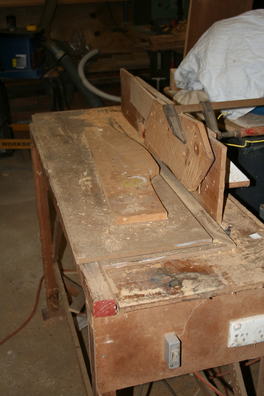
This simple jig, set up on my bandsaw, allowed me to quickly and neatly trim the waste from the wedges and tenons.
The joints are trimmed and the sashes are ready for sanding, before the trimming of the stiles, bevelling of the bottom of the lower sash's, grooving the sides for the ropes and fitting into the frames. There's still a long way to go....